
A driving device and control method for a permanent magnet linear motor

A permanent magnet linear motor and control method technology, applied in the control of motor speed or torque, AC motor control, electromechanical devices, etc., can solve problems such as restricting application, efficiency, and reliability, and achieve the effect of improving efficiency

Active Publication Date: 2018-06-01
SHANGHAI MICRO ELECTRONICS EQUIP (GRP) CO LTD
View PDF9 Cites 0 Cited by
  • Summary
  • Abstract
  • Description
  • Claims
  • Application Information

AI Technical Summary

Problems solved by technology

[0004] At present, the motor drive device technology used in lithography equipment, on the whole, has relatively large deficiencies in efficiency and reliability, which seriously restricts further applications.

Method used


Image

  • A driving device and control method for a permanent magnet linear motor
  • A driving device and control method for a permanent magnet linear motor
  • A driving device and control method for a permanent magnet linear motor

Examples


Embodiment Construction

[0030] Specific embodiments of the present invention will be described in detail below in conjunction with the accompanying drawings.

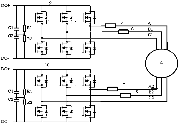
[0031] The driving device and control method of a permanent magnet linear motor described in the present invention is aimed at the defects of the prior art, and analyzes specific measures to improve efficiency and reliability. Taking a double-three-phase permanent magnet direct motor as the research object, The design of drive circuit, the automatic collection of fault points, the principle of fault switching, and the measures to improve reliability are analyzed, and a feasible reliability control scheme is described in detail.

[0032] The motor is characterized in that the mover is a double-three-phase winding coreless structure, the stator adopts a Halbach permanent magnet array, the back iron is designed to be very thin, and is evenly distributed and symmetrically fixed on both sides of the mover, which solves the problem of the traditional...


PUM


Abstract

The invention discloses a driving device for a permanent magnet linear motor, which is characterized in that the permanent magnet linear motor includes a stator and a mover, the mover is composed of ironless double-three-phase windings, and a three-wire winding of the permanent magnet linear motor is connected For the first inverter, another three-wire winding is connected to the second inverter; the coreless double three-phase winding is a double Y-shaped winding.

Description

technical field [0001] The invention relates to the field of integrated circuit equipment manufacturing, in particular to a driving device and a control method for a permanent magnet linear motor. Background technique [0002] In the current lithography equipment, large-area lithography is realized by controlling the workpiece table to expose silicon wafers multiple times. The basic functions of the workpiece table at high speed, high precision, high frequency response and large stroke cannot be separated from the permanent magnet linear motor technology. Specifically The application can be determined according to the structure of the precision workpiece table. It should not only satisfy the micro-displacement short-stroke high-precision drive, but also realize long-stroke high-speed repetitive movement and positioning to achieve high resolution, high engraving accuracy, high productivity, and low maintenance. rate key performance objectives. [0003] In order to improve th...

Claims


Application Information

Patent Timeline
Patent Type & Authority Patents(China)
IPC IPC(8): H02K41/03H02P25/06H02P27/06H02P4/00
Inventor 段占晓铁玉峰马凤霞连国栋贾辉
Owner SHANGHAI MICRO ELECTRONICS EQUIP (GRP) CO LTD
Learn More