Eureka AIR delivers breakthrough ideas for toughest innovation challenges, trusted by R&D personnel around the world.

Centrifugal farmland fertilizer applicator

A fertilizer applicator and centrifugal technology, applied in the field of centrifugal farmland fertilizer applicators, can solve the problems of inconvenient maintenance, high price, disadvantage and the like, and achieve the effects of convenient operation by one person, low manufacturing cost and simple structure

Inactive Publication Date: 2016-04-06
钟国平
View PDF5 Cites 3 Cited by
  • Summary
  • Abstract
  • Description
  • Claims
  • Application Information

AI Technical Summary

Problems solved by technology

[0002] In many places in our country, chemical fertilizers are generally applied by manual spraying. Due to the long time spent on manual fertilization, the chemical fertilizers cannot be turned under the soil in time, which is easy to cause the loss of fertility.
Artificial fertilization cannot quantitatively spread chemical fertilizers evenly on the farmland, which is easy to cause accumulation and loss of fertility, and cannot make chemical fertilizers evenly applied to crops.
Artificial fertilizers are sprinkled at a high height, which can easily cause the fertilizers to drift with the wind and affect the environment
Chemical fertilizers are generally corrosive to a certain extent, causing certain harm to the body of the fertilizer
Artificial fertilization takes up a lot of labor, which is not conducive to agricultural mechanized production. Although there are some fertilizer spreaders on the market, there are too many supporting devices and the volume is too large, which is not conducive to single-person operation. It is also expensive and inconvenient to maintain.

Method used


Image

  • Centrifugal farmland fertilizer applicator
  • Centrifugal farmland fertilizer applicator
  • Centrifugal farmland fertilizer applicator

Examples


Embodiment Construction

[0013] The following will clearly and completely describe the technical solutions in the embodiments of the present invention with reference to the accompanying drawings in the embodiments of the present invention. Obviously, the described embodiments are only some, not all, embodiments of the present invention. Based on the embodiments of the present invention, all other embodiments obtained by persons of ordinary skill in the art without making creative efforts belong to the protection scope of the present invention.

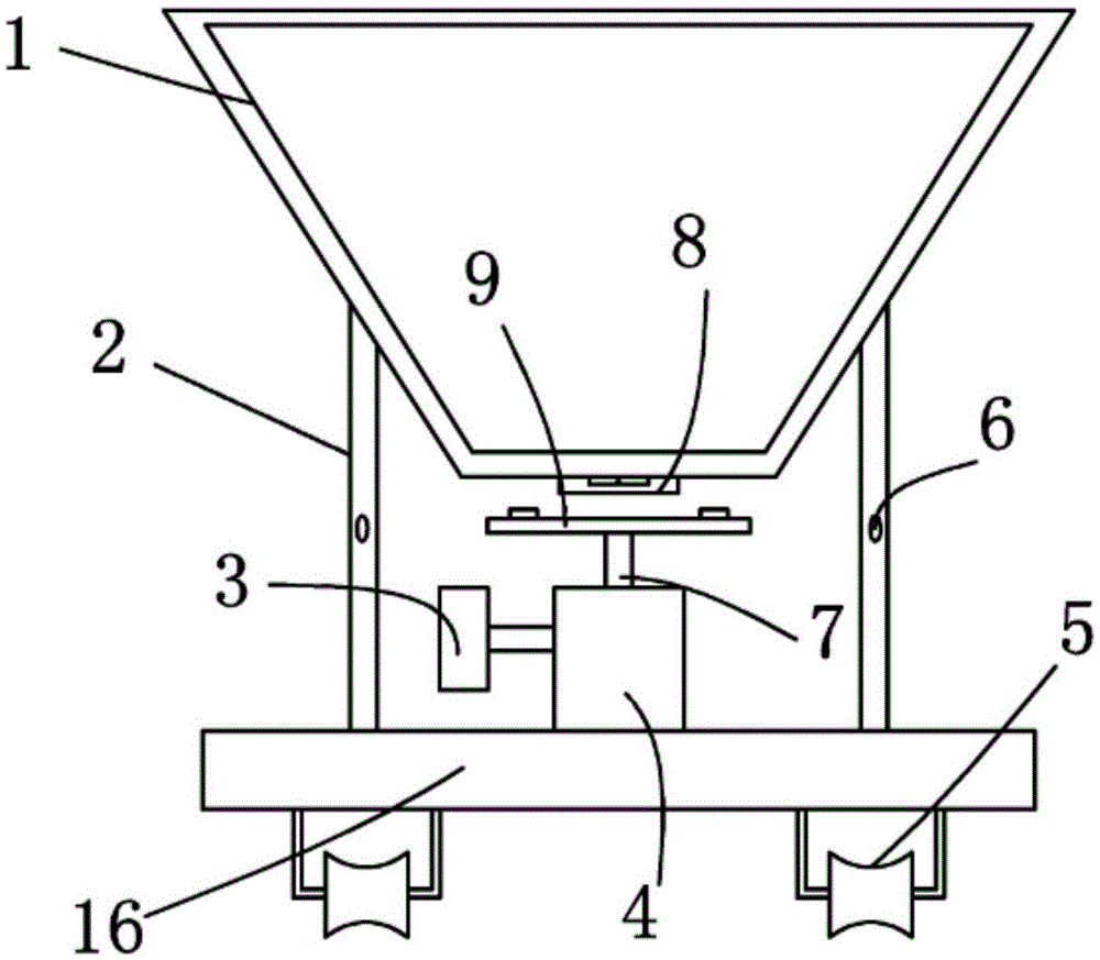
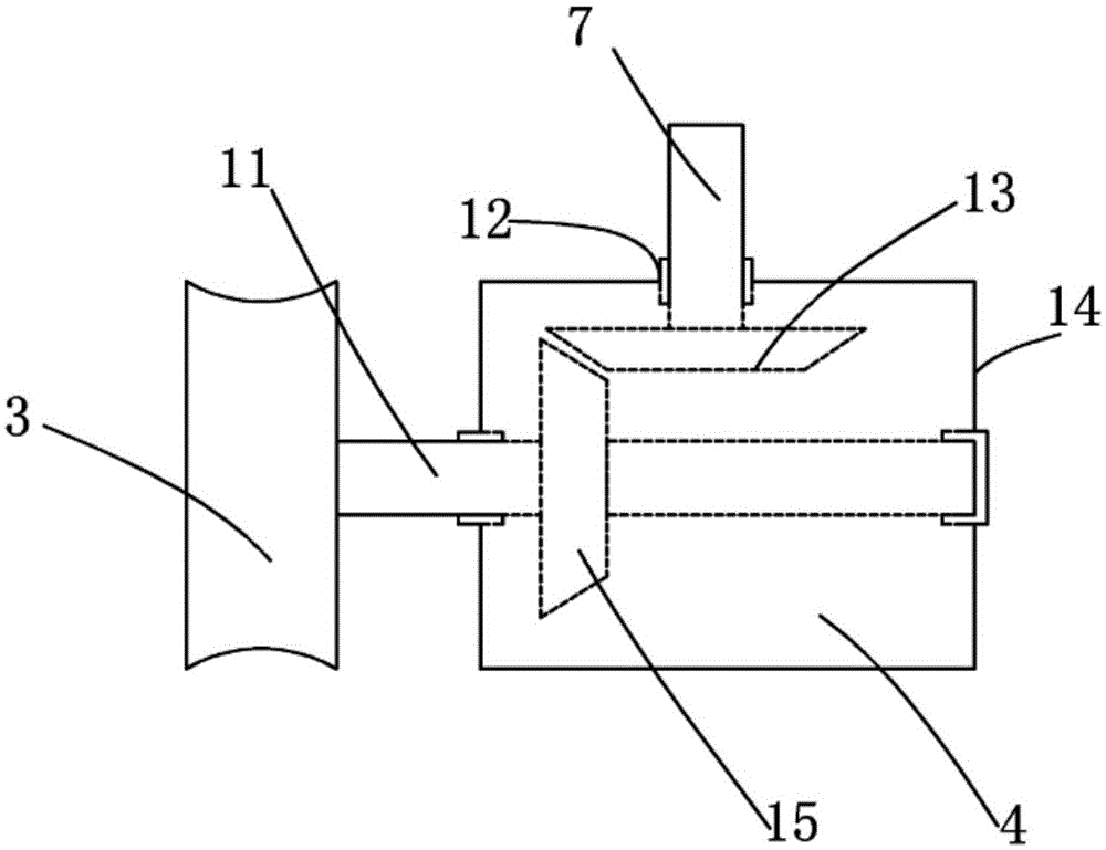
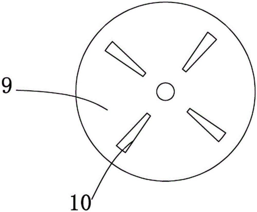
[0014] see Figure 1-3 , the present invention provides a technical solution: a centrifugal farmland fertilizer applicator, comprising a fertilizer hopper 1 and a base 16, the upper end surface of the base 16 is provided with a transmission device 4, the transmission device 4 includes a transmission device housing 14, the transmission device housing 14 The upper side of the inner cavity is plugged with the first transmission shaft 7, the joint of the transmiss...


PUM


Abstract

The invention discloses a centrifugal farmland fertilizer applicator. The centrifugal farmland fertilizer applicator comprises a fertilizer hopper and a base. A transmission device is arranged on the upper end face of the base and comprises a transmission device shell. A first transmission shaft is connected to the upper side of an inner cavity of the transmission device shell in an inserted mode. One end of the first transmission shaft is fixedly connected with a first conical gear. The other end of the first transmission shaft is fixedly connected with a fertilizer scattering tray. A second transmission shaft is connected to the left side of the inner cavity of the transmission device shell in an inserted mode. A transmission wheel is arranged on one side of the second transmission shaft. A second conical gear meshed with the first conical gear is arranged on the other side of the second transmission shaft. Hopper supports are arranged at the four corners of the upper end face of the base. The fertilizer hopper is fixedly connected to the upper ends of the fertilizer supports. A discharge port is reserved in the lower end face of the fertilizer hopper and located over the fertilizer scattering tray. Rolling wheels are evenly arranged on the lower end face of the base. By means of the centrifugal farmland fertilizer applicator, fertilizer can be scattered into farmland more uniformly, and the centrifugal farmland fertilizer applicator is simple in structure, small in size and low in manufacturing cost.

Description

technical field [0001] The invention relates to the technical field of agricultural machinery, in particular to a centrifugal farmland fertilizer applicator. Background technique [0002] In many places in our country, chemical fertilizers are generally applied by manual spraying. Due to the long time spent on manual fertilization, the chemical fertilizers cannot be turned under the soil in time, which is easy to cause the loss of fertility. Artificial fertilization cannot quantitatively and evenly sprinkle chemical fertilizers on the farmland, which is easy to cause accumulation and loss of fertility, and cannot make the chemical fertilizers evenly applied to the crops. Artificial fertilizers are sprinkled at a high height, which can easily cause the fertilizers to drift with the wind and affect the environment. Chemical fertilizers are generally corrosive to a certain extent, causing certain harm to the body of the fertilizers. Manual fertilization takes up a lot of labo...

Claims


Application Information

Patent Timeline
Patent Type & Authority Applications(China)
IPC IPC(8): A01C15/16
CPCA01C15/16Y02P60/21
Inventor 钟国平
Owner 钟国平
Why Eureka
Eureka Blog
Learn More