
Automatic paint sprayer and control unit thereof

An automatic paint spraying machine and control unit technology, applied in the direction of spraying devices, etc., can solve the problems of missing or multi-layered paint layers, increase labor intensity of workers, waste of paint and time, etc., to ensure quality, reduce labor intensity, Avoid spraying less or spraying more

Active Publication Date: 2016-04-06
苏州市赖氏喷漆机科技有限公司
View PDF9 Cites 6 Cited by
  • Summary
  • Abstract
  • Description
  • Claims
  • Application Information

AI Technical Summary

Problems solved by technology

However, in actual operation, due to the spraying of products of different sizes and the different process requirements of the products, the operator needs to pay attention to the spraying status of the automatic paint spraying machine at all times, so as to adjust the movement direction of the truss at any time. At the same time, according to different product requirements, its surface needs The number of sprayed paint layers is completely different, so the labor intensity of workers is increased, and it is easy to cause overspray due to carelessness, resulting in waste of paint and time. In addition, once the number of sprayed layers is negligent by the operator, it is easy to appear Leakage or multiple layers of spray paint layers cannot accurately meet customer requirements

Method used


Image

  • Automatic paint sprayer and control unit thereof
  • Automatic paint sprayer and control unit thereof

Examples


Embodiment Construction

[0028] The present invention will be further described below through specific examples.

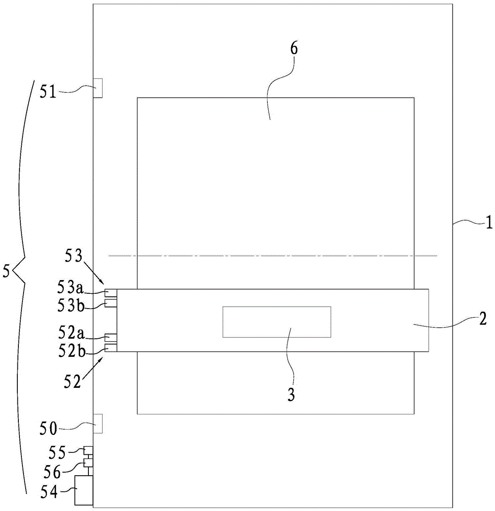
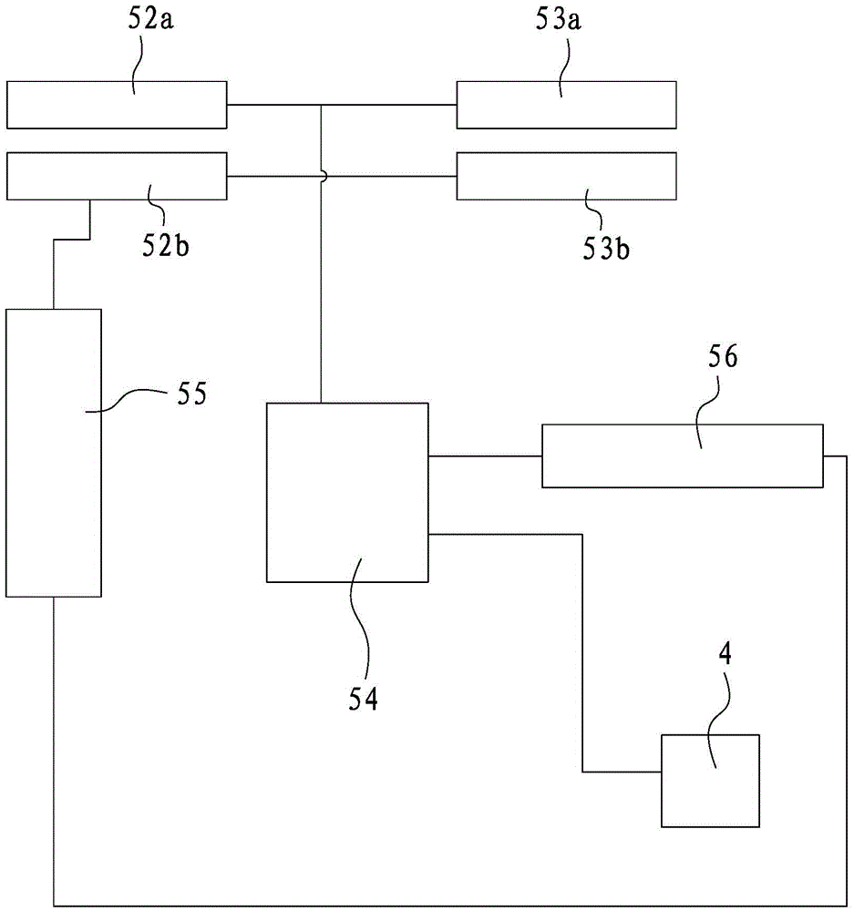
[0029] Such as figure 1 and 2 As shown, the automatic painting machine provided in this embodiment includes a machine cabin 1, a truss 2 that can move along the length direction of the machine cabin 1 and extends along the width direction of the machine cabin 1, and can move along the length direction of the truss 2 The paint spraying device 3 arranged on the truss 2, the first drive mechanism 4 for driving the truss 2 and the paint spraying device 3 to move, and the control unit 5 for controlling the operation of the automatic paint spraying machine. The painting device 3 includes a spray gun for painting. The first driving mechanism 4 includes a driver and a motor controlled by the driver.

[0030] The control unit 5 includes: sensing elements 50, 51; sensors 52, 53; PLC controller 54; counter 55;

[0031] Specifically, there are two sensing elements 50, 51, and the two sensing elem...


PUM


Abstract

The invention relates to an automatic paint sprayer and a control unit thereof. The control unit comprises a sensing part, a sensor, a PLC (Programmable Logic Controller), a counter and a relay, wherein the PLC is used for receiving a sensing signal of the sensor and controlling a first driving mechanism to drive a truss to move backwards according to the sensing signal; an on-off control electromagnetic valve for controlling on and off of a spray gun; the counter is respectively connected with the sensor and the relay and is used for sending a power-off signal to the relay when the counted number reaches a set value; the relay is arranged on a power supply circuit of the PLC and / or the first driving mechanism and is connected with the on-off control electromagnetic valve; the relay is cut off after receiving the power-off signal so that the on-off control electromagnetic valve, the PLC and the like stop working because power is off, and thus the paint sprayer is shut down. By adopting the control unit disclosed by the invention, the amount of paint-sprayed layers can be precisely controlled, over spraying is prevented, the labor intensity of workers is greatly alleviated, occurrence of insufficient spraying or over spraying is effectively prevented, the spraying quality is guaranteed, and waste of paint materials is reduced.

Description

technical field [0001] The invention relates to an automatic paint spraying machine, and also relates to a control unit of the automatic paint spraying machine. Background technique [0002] Automatic paint spraying machines are known, usually comprising a cabin, a truss movably arranged in the cabin, a painting device movably arranged on the truss, generally, the truss itself extends along the width direction of the cabin, and Its moving direction is the length direction of the cabin, and the painting device is movably arranged along the length direction of the truss. In this way, the painting device can actually move simultaneously along the X and Y directions perpendicular to each other, so as to realize the comprehensive painting of the product surface . [0003] For example, baking varnish for glass is characterized by various specifications, different sizes, and various colors. At present, in the field of automatic painting, automatic painting machines only carry out...

Claims


Application Information

Patent Timeline
Patent Type & Authority Applications(China)
IPC IPC(8): B05B13/04B05B12/12
CPCB05B12/122B05B13/0405
Inventor 赖建豪王静
Owner 苏州市赖氏喷漆机科技有限公司
Learn More