
Laser device fixing device and method for achieving temperature self-adaption through same

A technology of fixing devices and lasers, applied in feeding devices, large fixed members, automatic control devices, etc., can solve problems affecting surface processing quality, unstable cutting temperature, etc., and achieve sensitive and convenient self-adaptive process, easy to control, temperature control Compare the exact effect

Inactive Publication Date: 2016-04-06
HARBIN UNIV OF SCI & TECH
View PDF6 Cites 3 Cited by
  • Summary
  • Abstract
  • Description
  • Claims
  • Application Information

AI Technical Summary

Problems solved by technology

[0005] In order to solve the problem that the cutting temperature is unstable in the existing laser-assisted cutting process, thereby seriously affecting the quality of surface processing, the present invention further proposes a laser fixing device and a method for realizing temperature self-adaptation by using the device

Method used


Image

  • Laser device fixing device and method for achieving temperature self-adaption through same
  • Laser device fixing device and method for achieving temperature self-adaption through same
  • Laser device fixing device and method for achieving temperature self-adaption through same

Examples


specific Embodiment approach 1

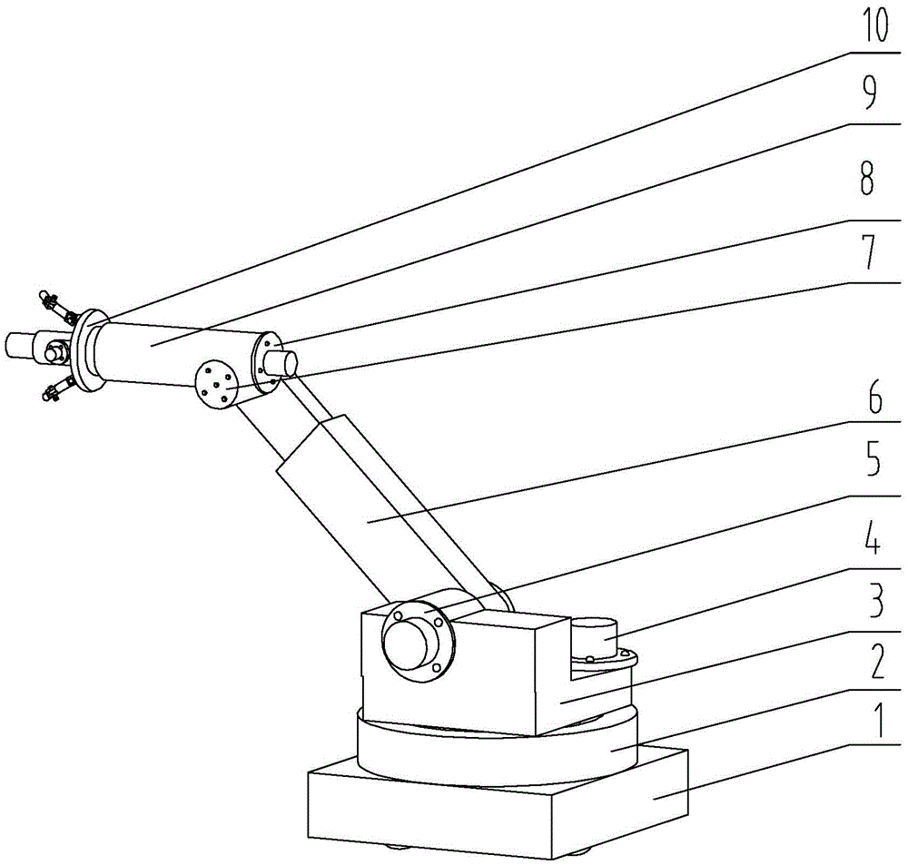
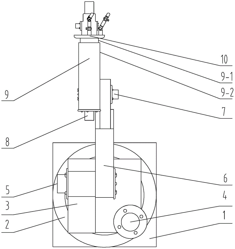
[0027] Specific implementation mode one: combine Figure 1 to Figure 3 Describe this embodiment. A laser fixing device described in this embodiment includes a base 1, a rotary mechanism, an extension mechanism, an adjustment mechanism, and a launch mechanism. The launch mechanism, the adjustment mechanism, the extension mechanism, and the rotation mechanism are arranged in sequence from front to back. The mechanism is set on the base 1,

[0028] The rotary mechanism includes a rotary base 2, a rotary table 3 and a first rotary motor 4, the rotary base 2 is fixed on the base 1, the rotary table 3 is arranged on the upper end surface of the rotary base 2, and the rotation between the rotary table 3 and the rotary base 2 connection, the first rotary motor 4 is vertically arranged on the rotary table 3, the housing of the first rotary motor 4 is fixedly connected to the rotary table 3, and the rotating shaft of the first rotary motor 4 is connected to the rotary seat 2,

[0029] ...

specific Embodiment approach 2

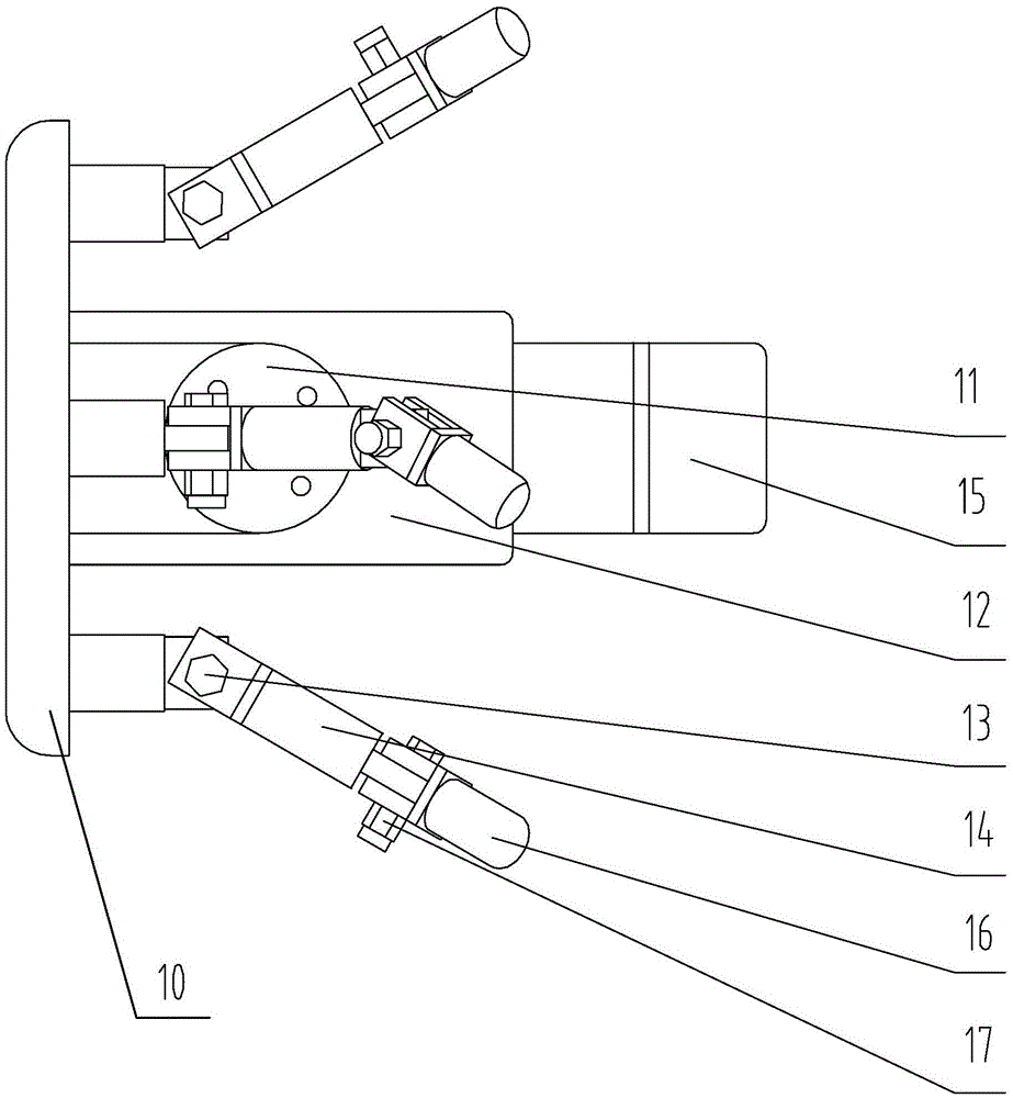
[0032] Specific implementation mode two: combination Figure 1 to Figure 3 Describe this embodiment, the rotating shaft 14 in this embodiment is connected to the connecting end surface 10 through the first stud 13, the infrared sensor 16 is connected to the rotating shaft 14 through the second stud 17, and the second stud 17 is connected to the rotating shaft 14. A double-ended stud 13 is vertically arranged with the second double-ended stud 17 . The undisclosed technical features in this embodiment are the same as those in the first embodiment.

specific Embodiment approach 3

[0033] Specific implementation mode three: combination Figure 1 to Figure 3 This embodiment will be described. In this embodiment, the inner housing 9-1 and the outer housing 9-2 are connected by bearings. The undisclosed technical features in this embodiment are the same as those in the first or second specific embodiment.


PUM


Abstract

The invention discloses a laser device fixing device and a method for achieving temperature self-adaption through the laser device fixing device and relates to a laser cutting device and a cutting temperature control method. The laser device fixing device and the method for achieving temperature self-adaption through the laser device fixing device aim at solving the problem that due to the fact that the cutting temperature is not stable in the existing laser-assisted cutting process, the surface machining quality is seriously affected. The laser device fixing device comprises a base, a rotating mechanism, a stretching mechanism, an adjusting mechanism and a transmitting mechanism. The transmitting mechanism, the adjusting mechanism, the stretching mechanism and the rotating mechanism are sequentially arranged from front to back. The rotating mechanism is arranged on the base. The transmitting mechanism comprises a connecting end face, a fifth rotating motor, a second hydraulic cylinder, a laser transmitter, a plurality of rotating shafts and a plurality of infrared ray inductors. The method for achieving temperature self-adaption includes the steps of establishing a temperature database, monitoring temperature, feeding back information and adjusting current. The laser device fixing device and the method for achieving temperature self-adaption through the laser device fixing device are used for laser heating assisted cutting.

Description

technical field [0001] The invention relates to a laser fixing device and a method for realizing temperature self-adaptation by using the device. Background technique [0002] Laser heating assisted milling technology is to irradiate a high-energy laser beam on the material removal area, increase the local temperature of the workpiece material in a short time, change the cutting performance of the material, and then use the tool for processing. By heating the material, the plasticity of the material is improved, the yield strength is reduced to below the fracture strength, the cutting force is reduced, the tool wear is reduced, and the cutting chatter is reduced, thereby achieving the purpose of improving processing efficiency, reducing cost, and improving the quality of the processed surface. [0003] Precise temperature control is the basis for laser heating assisted milling. The precise temperature control depends on the processing power and scanning speed of the laser. ...

Claims


Application Information

Patent Timeline
Patent Type & Authority Applications(China)
IPC IPC(8): B23P25/00B23Q1/25B23Q17/00B23Q15/00
CPCB23P25/003B23Q1/25B23Q15/00B23Q17/00
Inventor 吴雪峰赵博文苑忠亮
Owner HARBIN UNIV OF SCI & TECH
Learn More