Ground breaking device

A ground and positioning hole technology, applied in construction, building maintenance, instruments, etc., can solve the problems of high penetration requirements, low destruction efficiency, and short construction period

Pending Publication Date: 2022-04-29
HUADONG BUILDING CO LTD OF CHINA CONSTR FIFTH ENG BUREAU +1
View PDF0 Cites 0 Cited by
  • Summary
  • Abstract
  • Description
  • Claims
  • Application Information

AI Technical Summary

Problems solved by technology

[0002] Due to the short overall construction period, fast pace, and high requirements for interspersed procedures of factory building projects, the investment in on-site temporary construction facilities needs to adapt to the development requirements of construction period improvement and rapid construction system, and construct as efficiently and quickly as possible. However, the current construction The required multi-process steps are carried out synchronously to ensure construction efficiency. At present, in the construction site, it is necessary to demolish the original open space and after the construction is completed, it is necessary to re-bury the pipeline for the planned route, which also needs to be demolished, but At present, the demolition is mainly carried out by hand-held air picks, and some grounds are paved with large bricks and stones. The efficiency of direct destruction by air picks is low, and it is laborious to move, and the labor cost is high. At the same time, the noise is large, which does not meet the requirements of green energy conservation. construction requirements

Method used


Image

  • Ground breaking device
  • Ground breaking device
  • Ground breaking device

Examples


Embodiment Construction

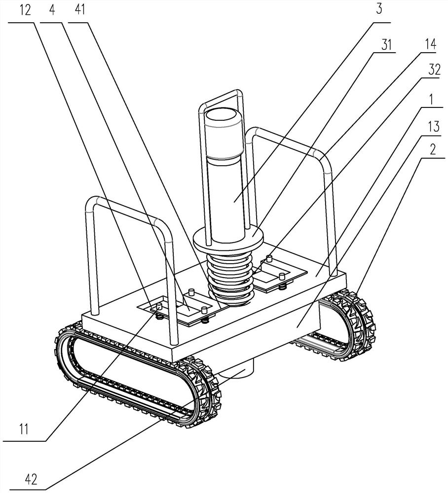
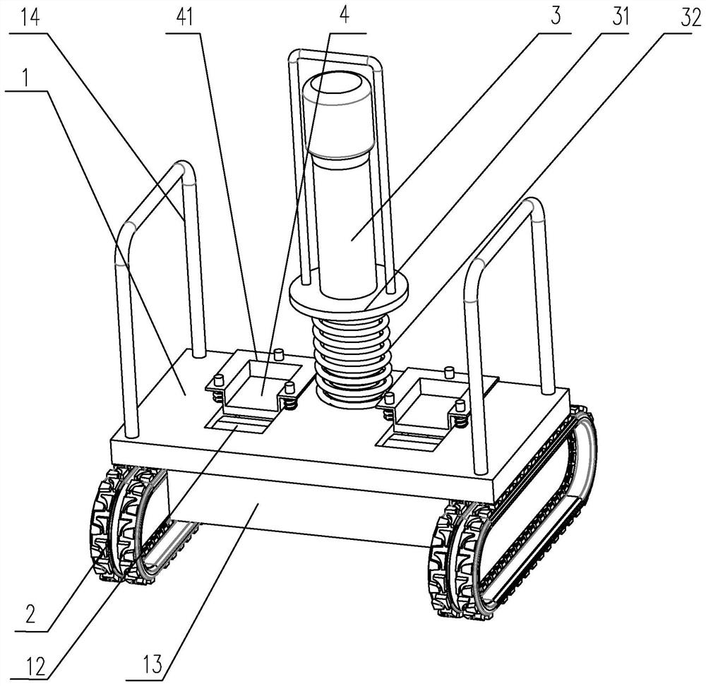
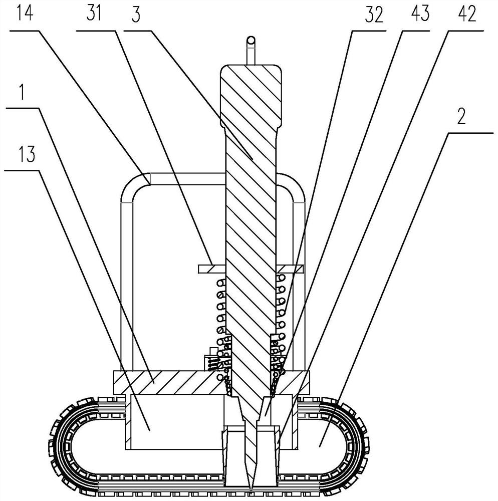
[0019] The embodiment of ground breaking device of the present invention is such as Figure 1 to Figure 3 Shown: includes a base 1, track wheels 2 are provided on both sides of the base 1, a positioning hole is opened on the central axis of the base 1, a pneumatic pick 3 is pierced in the positioning hole, and the upper edge of the pneumatic pick 3 A positioning plate 31 is arranged in the circumferential direction, and a buffer spring 32 is also sleeved on the jack 3. The buffer spring 32 is arranged in conflict between the positioning plate 31 and the base 1, and the base 1 is on both sides of the positioning hole. Stepping grooves are respectively provided, and the stepping grooves include a forefoot groove and a heel groove 12, and the forefoot groove and the heel groove 12 are connected by a smooth connection surface, and a pedal 4 is slid along the height direction in the forefoot groove. , the pedal 4 is provided with a positioning flange 41 along the circumferential di...


PUM


Abstract

The invention discloses a ground breaking device which comprises a base, crawler wheels are arranged on the two sides of the base, a positioning hole is formed in the central axis of the base, an air pick is arranged in the positioning hole in a penetrating mode, a positioning plate is arranged on the air pick in the circumferential direction, and a buffer spring abuts against the position between the positioning plate and the base. A positioning hole is formed in the base, treading grooves are formed in the positions, on the two sides of the positioning hole, of the base respectively and comprise a half sole groove and a heel groove, a pedal is arranged in the half sole groove in a sliding mode, a positioning flange is arranged on the pedal in the circumferential direction, a guide hole is formed in the positioning flange, and a guide column is arranged in the position, corresponding to the guide hole, of the base. The guide columns are in sliding fit with the corresponding guide holes, the guide columns are sleeved with reset springs, the reset springs abut against the position between the positioning flange and the base, a check ring is connected between the two pedals and surrounds the air pick, and the end, close to the ground, of the check ring is sharp. The structure is simple, the forcible entry efficiency is high, and the construction effect is effectively improved.

Description

technical field [0001] The invention relates to the technical field of building construction, in particular to a ground breaking device. Background technique [0002] Due to the short overall construction period, fast pace, and high requirements for interspersed procedures of factory building projects, the investment in on-site temporary construction facilities needs to adapt to the development requirements of construction period improvement and rapid construction system, and construct as efficiently and quickly as possible. However, the current construction The required multi-process steps are carried out synchronously to ensure construction efficiency. At present, in the construction site, it is necessary to demolish the original open space and after the construction is completed, it is necessary to re-bury the pipeline for the planned route, which also needs to be demolished, but At present, the demolition is mainly carried out by hand-held air picks, and some grounds are...

Claims


Application Information

Patent Timeline
IPC IPC(8): E04G23/08G10K11/16
CPCE04G23/08G10K11/16
Inventor 楼磊浩付飞辉刘振华龚良伟颜文武
Owner HUADONG BUILDING CO LTD OF CHINA CONSTR FIFTH ENG BUREAU
Why Eureka
Try Eureka