Charging hydraulic tool

A hydraulic tool, rechargeable technology, applied in the direction of manufacturing tools, portable mobile devices, etc., can solve the problems of increasing safety hazards, inconsistent crimping direction of insulated wire copper joints, safety hazards, etc., to achieve easy on-site portability, reduce tool investment, The effect of improving work efficiency

Active Publication Date: 2016-04-06
STATE GRID ZHEJIANG HANGZHOU CITY FUYANG DISTRICT POWER SUPPLY CO LTD +2
View PDF10 Cites 1 Cited by
  • Summary
  • Abstract
  • Description
  • Claims
  • Application Information

AI Technical Summary

Problems solved by technology

[0002] In the process of electric power work, a large number of crimping operations of copper joints of low-voltage insulated wires need to be completed every year. The entire operation process includes four steps: wire cutting, insulation stripping, copper joints, and compression molding. In these four steps, it is necessary to At least four tools including hydraulic cutting tools, manual insulation stripping tools, insulation clamping tools, and hydraulic crimping tools are used. Each tool must be equipped with a hydraulic drive part, and some components also need to be equipped with a motor drive part. Therefore, the on-site operators have a heavy task of carrying tools, and the on-site crimping operation of low-voltage insulated conductor copper joints often needs to be carried out on the cable layout site, or even on high ground. The on-site operators carry so many and such heavy tools for climbing The operation is not only very inconvenient, but also has great potential safety hazards
[0003] In addition, during on-site operations, the installation position of the object to be operated will vary according to the surrounding environment, resulting in inconsistent crimping directions of copper joints of insulated wires. In actual operation, in most cases, the crimping direction It is inconsistent with the normal gesture direction of the operator. If conventional tools are used at this time, the operator needs to change the normal force direction, which brings great inconvenience to actual engineering operations and sometimes increases safety hazards.

Method used


Image

  • Charging hydraulic tool
  • Charging hydraulic tool
  • Charging hydraulic tool

Examples


Embodiment Construction

[0021] Refer to attached picture.

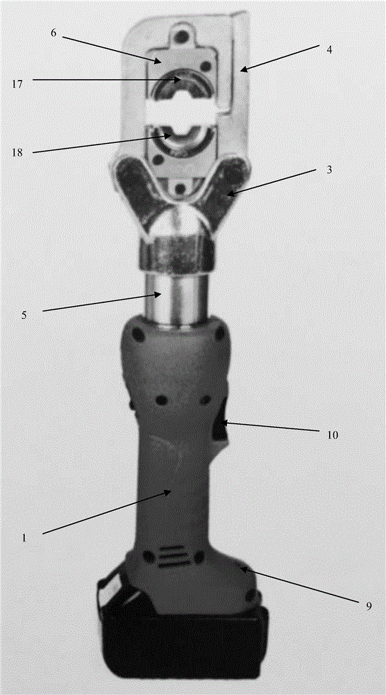
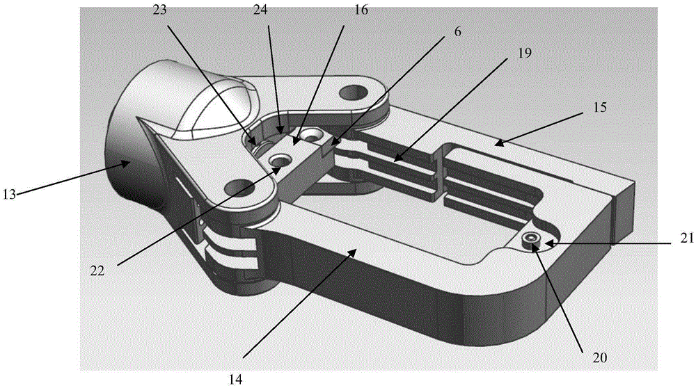
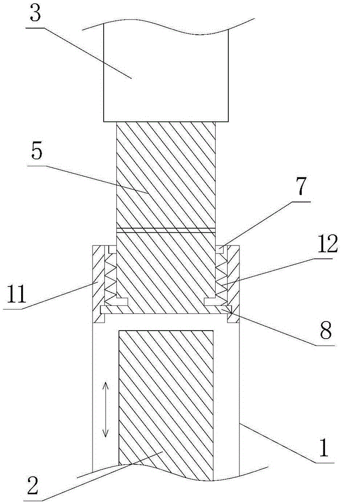
[0022] The rechargeable hydraulic tool of the present invention includes a handle 1, a hydraulic drive part 2 and an end structure 3, the end structure 3 includes a working head 4, and a replaceable working part 6 is arranged on the working head 4, and the replaceable working part 6 For matching jaws, cutters or crimping dies. The rechargeable hydraulic tool also includes a connection mechanism 5 between the hydraulic drive part 2 and the end structure 3. The connection mechanism 5 is a rotatable part, and the rotatable connection mechanism 5 can transmit the jacking force of the hydraulic drive part 2. The end structure 3 rotates 360° without dead angle.

[0023] The connecting mechanism 5 is a damping rotating shaft, and one end of the connecting mechanism 5 extends into the handle 1 and is flexibly connected with the handle 1. The flexible connection here refers to an unfixed connection, and the connecting mechanism 5 can reciprocate up ...


PUM


Abstract

The invention provides a charging hydraulic tool which comprises a handle, a hydraulic driving part and an end part structure, wherein the end part structure comprises a working head; a replaceable working component is arranged on the working head; the charging hydraulic tool further comprises a connecting mechanism used for connecting the hydraulic driving part with the end part structure; and the connecting mechanism adopts a rotatable component, and can enable the end part structure to rotate by 360 degrees while transmitting a jacking action force of the hydraulic driving part. The charging hydraulic tool can realize multiple operation functions, is convenient to use, and has a wide application prospect, and moreover, the end part structure can rotate by multiple angles.

Description

technical field [0001] The invention relates to the field of electric working tools, in particular to a rechargeable hydraulic tool. Background technique [0002] In the process of electric power work, a large number of crimping operations of copper joints of low-voltage insulated wires need to be completed every year. The entire operation process includes four steps: wire cutting, insulation stripping, copper joints, and compression molding. In these four steps, it is necessary to At least four tools including hydraulic cutting tools, manual insulation stripping tools, insulation clamping tools, and hydraulic crimping tools are used. Each tool must be equipped with a hydraulic drive part, and some components also need to be equipped with a motor drive part. Therefore, the on-site operators have a heavy task of carrying tools, and the on-site crimping operation of low-voltage insulated conductor copper joints often needs to be carried out on the cable layout site, or even on...

Claims


Application Information

Patent Timeline
IPC IPC(8): B25F3/00B25F5/00B25F5/02
CPCB25F3/00B25F5/00B25F5/02
Inventor 俞伟陈运罗良夏林君费军炜盛成海胡晓哲沈文良周涛
Owner STATE GRID ZHEJIANG HANGZHOU CITY FUYANG DISTRICT POWER SUPPLY CO LTD
Why Eureka
Try Eureka