Single-freedom-degree rotating joint of underwater robot

A technology of underwater robots and rotary joints, which is applied in the field of robots, can solve the problems of unfavorable joint sealing of rods and the installation of rod shells, etc., and achieve the effect of simplifying joint structure and sealing structure and good sealing effect

Active Publication Date: 2016-04-06
HARBIN INST OF TECH
View PDF7 Cites 5 Cited by
  • Summary
  • Abstract
  • Description
  • Claims
  • Application Information

AI Technical Summary

Problems solved by technology

[0003] The purpose of the present invention is to solve the problem that the existing single-degree-of-freedom rotary joint of the underwater robot is easy to cause the mutual connectio

Method used


Image

  • Single-freedom-degree rotating joint of underwater robot
  • Single-freedom-degree rotating joint of underwater robot
  • Single-freedom-degree rotating joint of underwater robot

Examples


specific Embodiment approach 1

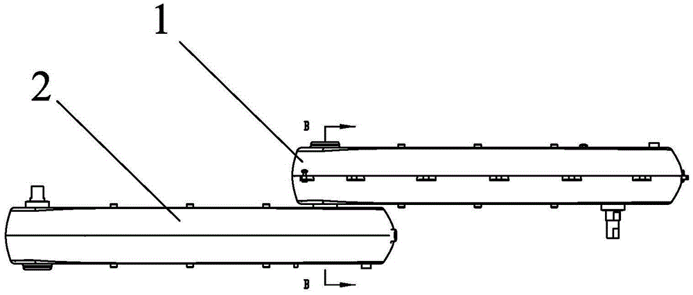
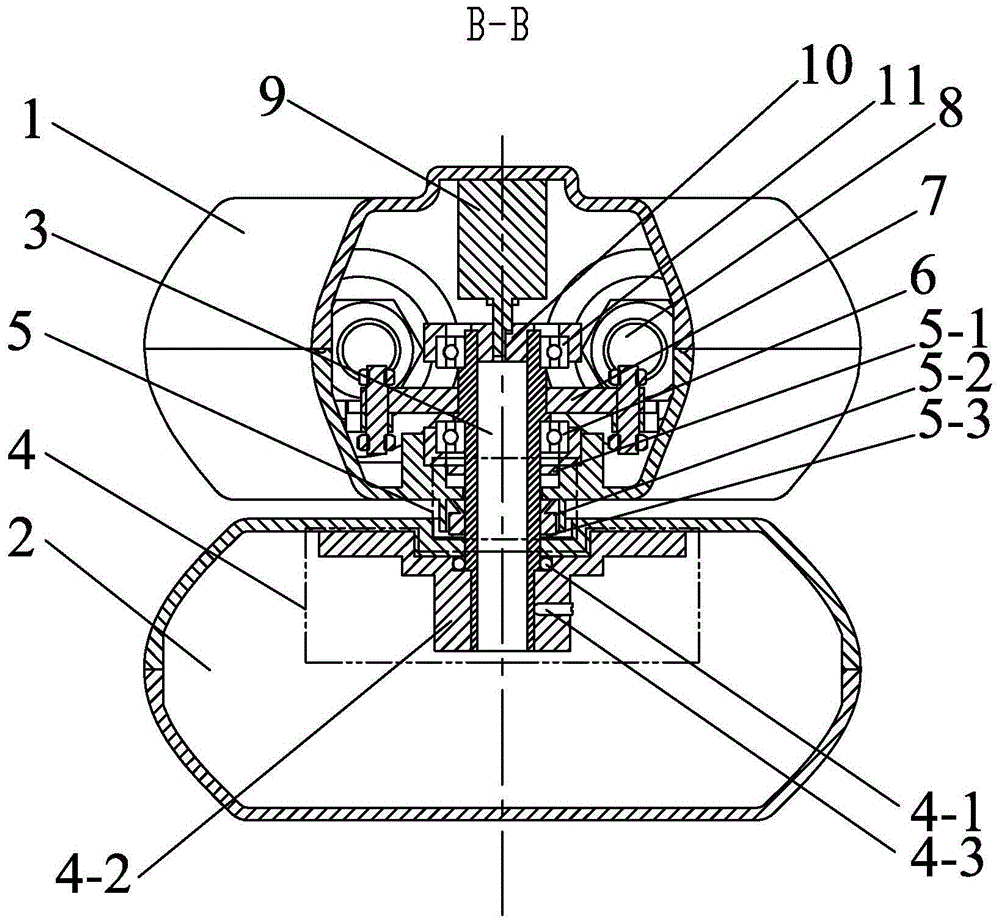
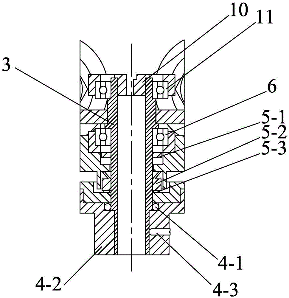
[0012] Specific implementation mode one: combine Figure 1 to Figure 3 Describe this embodiment, this embodiment is an underwater robot single-degree-of-freedom rotary joint, which includes a fixed base 1, a rotating base 2, a rotating shaft 3, a static sealing mechanism 4, a dynamic sealing mechanism 5, a first bearing 6, lever 7, two drivers 8 and encoder 9,

[0013] The fixed base 1 and the rotating base 2 are set up and down, the rotating shaft 3 is vertically installed in the fixed base 1 and the rotating base 2, and the connection between the rotating shaft 3 and the fixed base 1 and the rotating base 2 passes through The dynamic sealing mechanism 5 is sealed, the inside of the rotating base 2 is sealed and connected with the rotating shaft 3 through the static sealing mechanism 4, the encoder 9 is installed on the upper end of the rotating shaft 3 in the fixed base 1, and the lever 7 and the first bearing 6 are sequentially set on the On the rotating shaft 3, the lever...

specific Embodiment approach 2

[0022] Specific implementation mode two: combination Figure 1 to Figure 3 To describe this embodiment, the rotating shaft 3 of this embodiment is provided with a protruding shoulder, and the lever 7 is clipped on the protruding shoulder of the rotating shaft 3 . Set it up like this: Provide positioning for the lever. Other compositions and connections are the same as in the first embodiment.

specific Embodiment approach 3

[0023] Specific implementation mode three: combination Figure 1 to Figure 3 The present embodiment will be described. The output end of the encoder 9 of the present embodiment is a D-shaped shaft. The benefit of such setting is: it is convenient to connect with the rotating shaft 3 . Other compositions and connections are the same as those in the second embodiment.


PUM


Abstract

The invention relates to a single-freedom-degree rotating joint, in particular to a single-freedom-degree rotating joint of an underwater robot. The single-freedom-degree rotating joint aims at solving the problems that connection between rod pieces easily caused to an existing single-freedom-degree rotating joint of an underwater robot is not beneficial to sealing of the joint and installation of rod piece shells. A rotating shaft (3) vertically penetrates into a fixed base (1) and a rotary base (2), the joint between the rotating shaft (3) and the fixed base (1) and the joint between the rotating shaft (3) and the rotary base (2) are sealed through a dynamic sealing mechanism (5), the interior of the rotary base (2) is connected with the rotating shaft (3) in a sealed mode through a static sealing mechanism (4), an encoder (9) is installed at the upper end of the portion, in the fixed base (1), of the rotating shaft (3), the rotating shaft (3) is sequentially sleeved with a lever (7) and a first bearing (6), two tangent planes on the upper portion of the lever (7) and the upper portion of the rotating shaft (3) are matched to achieve linkage, and the tail ends of two drivers (8) are connected with one end of the lever (7). The single-freedom-degree rotating joint is especially suitable for frog-swimming-imitative robots.

Description

technical field [0001] The invention relates to a single-degree-of-freedom rotary joint of an underwater robot, which is a mechanism that drives the joint to rotate by using the principle of leverage, and realizes a compact and waterproof mechanism through the seal of the shaft, and belongs to the field of robots Background technique [0002] Due to the demand for marine resource development, bionic underwater propulsion robots have attracted extensive attention from scholars at home and abroad in recent years. In order to adapt to the joint rotation driven by the linear drive through the lever principle, the design of the single-degree-of-freedom rotary joint of the underwater robot is essential. Lever actuation provides an easy way to actuate linear actuators such as pneumatic muscles and cylinders. However, the mutual connection between the rods is not conducive to the sealing of the joints and the installation of the rod housings. Contents of the invention [0003] T...

Claims


Application Information

Patent Timeline
IPC IPC(8): B25J17/00F16J15/06F16J15/18
CPCB25J17/00F16J15/004F16J15/061F16J15/18
Inventor 樊继壮赵杰张伟孔彭城
Owner HARBIN INST OF TECH
Why Eureka
Try Eureka