Rough yarn feeding type rear top roller rubber roller device and ring spinning frame with same

A feed-in, roving technology used in spinning machines, continuous-winding spinning machines, textiles and papermaking, etc., to achieve the effect of facilitating maintenance and maintenance, good processing performance, and good bearing capacity

Pending Publication Date: 2016-04-06
JINGWEI TEXTILE MASCH CO LTD
View PDF7 Cites 0 Cited by
  • Summary
  • Abstract
  • Description
  • Claims
  • Application Information

AI Technical Summary

Problems solved by technology

However, the existing back top roller top rol

Method used


Image

  • Rough yarn feeding type rear top roller rubber roller device and ring spinning frame with same
  • Rough yarn feeding type rear top roller rubber roller device and ring spinning frame with same

Examples


Example Embodiment

[0014] The technical scheme of the present invention will be further described in detail below with reference to the drawings and embodiments.

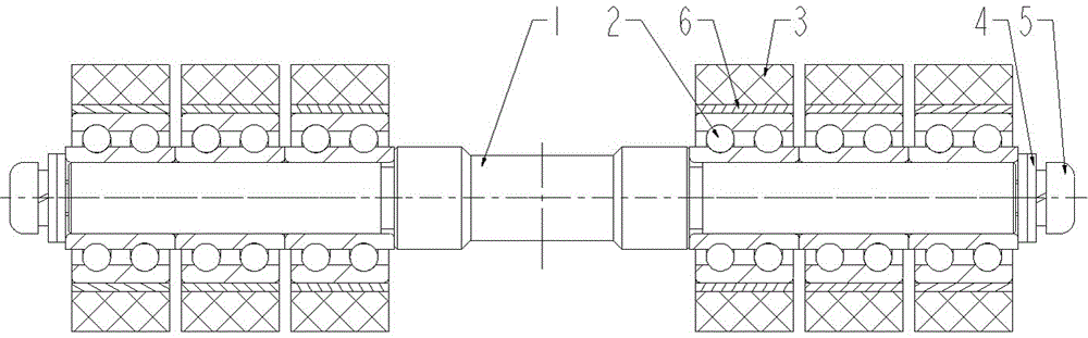
[0015] Such as figure 2 As shown, a roving feeding type rear top roller top roller device includes: rear top roller mandrel 1, special bearing 2, rubber roller 3, washer 4, screw 5 and aluminum bushing 6, and rear top roller mandrel 1 There are 2 spindles on the upper, and each spindle is equipped with a number of special bearings 2. The special bearing 2 is a double-row ball bearing whose inner ring width is greater than that of the outer ring. Oil ring, the width of the inner ring of the special bearing 2 is 6-15mm, and the diameter of the outer ring is Φ15-Φ20mm. The inner ring of the special bearing 2 is completely attached to the rear top roller mandrel 1, and the adjacent special bearing 2 is set between There is a gap to ensure that the outer ring of each special bearing 2 can rotate freely. The outer ring of the special bearing...


PUM

PropertyMeasurementUnit
Widthaaaaaaaaaa
Diameteraaaaaaaaaa
Widthaaaaaaaaaa

Abstract

The invention relates to a rough yarn feeding type rear top roller rubber roller device which comprises a rear top roller mandrel, special bearings, aluminum bushings and rubber rollers. At least two spindle positions are arranged on the rear top roller mandrel, each spindle position is provided with the corresponding multiple special bearings, the inner rings of the special bearings are completely attached to the rear top roller mandrel, gaps are formed between the adjacent special bearings to ensure that the outer rings of all the special bearings can rotate freely, the aluminum bushings are installed on the outer rings of the special bearings, and the outer surfaces of the aluminum bushings are wrapped with the rubber rollers. The special bearings are adopted, the outer rings of the special bearings and the rubber rollers can independently rotate, and thus the purpose that different coarse yarns on all the spindle positions are fed in and discharged out at different speeds is achieved. Meanwhile, the rough yarn feeding type rear top roller rubber roller device is compact in structure, convenient to disassemble and replace and beneficial to maintenance and preserving, and the special bearings have good bearing capability and meet the heavy and pressed spinning technology.

Description

Technical field [0001] The invention relates to a roving feeding type drafting transmission device, in particular to a roving feeding type rear top roller top roller device and a ring spinning frame used in the same. Background technique [0002] The rear top roller top roller device widely used on the existing ring spinning frame, such as figure 1 As shown, two spindles can be controlled at the same time, but when a single roving or multiple rovings of each spindle are fed, the roving passes through the surface of the same rubber roller and can only be output at the same speed. At present, when feeding multiple rovings for each spindle position, especially when spinning dyed yarn, each roving is required to output at different speeds, and even one or two rovings are required to be output after a temporary stop. Therefore, the top rear roller device should have an independent rotating structure. However, the existing rear top roller top roller device cannot meet the above requir...

Claims


Application Information

Patent Timeline
IPC IPC(8): D01H5/76D01H1/02
CPCD01H1/02D01H5/76
Inventor 李朋高淑丽郭艳史文娟王建根田克勤剌志勇郭红
Owner JINGWEI TEXTILE MASCH CO LTD
Why Eureka
Try Eureka