Suspension type underground hydraulic rod type pumping production device

A technology of oil production device and hydraulic rod, which is applied in the field of mechanical oil production, can solve the problems of long operation period, complicated operation procedures, wellbore wax deposition, etc., and achieve the effect of reducing operation cost, simplifying operation process and improving maintenance-free period

Inactive Publication Date: 2016-04-06
PETROCHINA CO LTD
View PDF6 Cites 3 Cited by
  • Summary
  • Abstract
  • Description
  • Claims
  • Application Information

AI Technical Summary

Problems solved by technology

However, this technology needs to lower the hydraulic pipe and the oil pipe together, the operation procedure is more complicated, and the operation cycle is longer
[0003] At the same time, due to the low temperature, which is lower than the freezing point of the wax, the wellbore will be waxed, and the cross section of the tubing will become smaller and blockage, which will affect the normal production of the oil well and even cause the oil well to stop production.

Method used


Image

  • Suspension type underground hydraulic rod type pumping production device

Examples


Embodiment 1

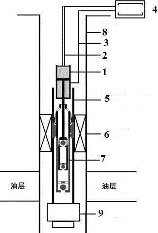
[0018] This embodiment provides a suspended downhole hydraulic rod pump oil extraction device, which includes a hydraulic cylinder 1, a hydraulic pipe 3 communicating with the hydraulic cylinder 1, a hydraulic control cabinet 4 and a rod pump 7, and the upper end of the hydraulic cylinder 1 communicates with There is a hollow sucker rod 2, the other end of the hollow sucker rod 2 and the hydraulic pipe 3 are connected to the hydraulic control cabinet 4, the rod type oil pump 7 is connected to the hydraulic cylinder, and the rod type oil pump 7 is set on the oil pipe 5, the hydraulic oil cylinder is set above the oil pipe 5, the lower part of the oil pipe 5 is provided with a support slip 9, and the oil pipe 5 is provided with a packer 6.

[0019] Before going into the well, connect the hydraulic cylinder 1 with the hydraulic pipe 3 and the hollow sucker rod 2, and debug the hydraulic control cabinet 4 to ensure that the direction of the liquid drive device is sensitive; 1. Aft...

Embodiment 2

[0023] On the basis of embodiment 1, this embodiment provides a kind of figure 1 In the suspended downhole hydraulic rod pump oil production device shown, the hydraulic control cabinet 4 includes an electrical control box and a heating control box, and the electrical control box is mainly used to control the starting of the motor and the reversing of the liquid drive device; Hydraulic oil, the heat is transferred to the hollow sucker rod 2 and then to the wellbore along with the hydraulic oil, which can effectively prevent the wellbore from waxing.

[0024] In this embodiment, the packer 6 is a KZ311 packer, which adopts a two-stage sealing method of expansion and self-sealing, and the hollow sucker rod 2 completes the sealing and unsealing to realize the casing 8 oil production.

[0025] The thrust of the hydraulic cylinder 1 is 0-1.5m, the rated thrust can reach 25000-35000N, and the medium temperature meets 0-150°C. The hydraulic pipe 3 is made of 316L stainless steel, whi...


PUM


Abstract

The invention provides a suspension type underground hydraulic rod type pumping production device which comprises a hydraulic cylinder, a hydraulic pipe communicated with the hydraulic cylinder, a hydraulic control cabinet and a rod type oil-well pump. A hollow sucker rod is communicated to the upper end of the hydraulic cylinder. The hollow sucker rod and the other end of the hydraulic pipe are connected with the hydraulic control cabinet. The rod type oil-well pump is connected with the hydraulic cylinder. The rod type oil-well pump is arranged in an oil pipe. The hydraulic cylinder is arranged above the oil pipe. The lower portion of the oil pipe is provided with a supporting slip. The oil pipe is sleeved with a packer. Pipe rod eccentric wear is eliminated, and the oil well maintenance-free period can be prolonged; the hollow sucker rod is adopted as a hydraulic transmission pipe, the heat of high-temperature hydraulic oil can be transferred to a well shaft, and paraffinning is effectively prevented. The device adopts a casing pipe oil extraction mode, only one or two oil pipes are needed, the operation process is simplified, and the operation cost is reduced.

Description

technical field [0001] The invention belongs to the technical field of mechanical oil extraction, and in particular relates to a suspended downhole hydraulic rod pump oil extraction device. Background technique [0002] The basic working principle of hydraulic (hydraulic drive) rodless oil recovery technology is that the electronic control system controls the hydraulic control system to generate alternating high-pressure oil, which is transmitted to the hydraulic drive propeller through the pressure transmission pipe to make it do reciprocating linear motion, thereby driving the plunger pump Reciprocating motion realizes the purpose of lifting crude oil from underground to the surface. This technology currently has the advantages of long pump inspection period, low operating cost, low maintenance cost, and high system efficiency. However, this technology needs to lower the hydraulic pipe together with the oil pipe, the operation procedure is relatively complicated, and the ...

Claims


Application Information

Patent Timeline
Patent Type & Authority Applications(China)
IPC IPC(8): E21B43/00
CPCE21B43/121
Inventor 刘天宇甘庆明李佰涛张磊杨海涛魏韦呼苏娟庞洁
Owner PETROCHINA CO LTD
Why Eureka
Try Eureka