
Mechanical connecting structure of shield machine sealing device

A technology of mechanical connection structure and sealing device, applied in mining equipment, earthwork drilling, tunnels, etc., can solve the problems of construction and surrounding environment, affecting normal excavation, separation of sand and pebbles, etc., to achieve stable and effective control and production efficiency The effect of high, low operational risk

Inactive Publication Date: 2016-04-06
陈杰
View PDF0 Cites 0 Cited by
  • Summary
  • Abstract
  • Description
  • Claims
  • Application Information

AI Technical Summary

Problems solved by technology

[0002] Existing shield machines are generally suitable for various surrounding rocks with a certain self-stabilization ability, low moisture content or no water in the excavation surface, and are suitable for soils such as sand, gravel, consolidated silt, clay and eggs in diluvial layers. When encountering sand and pebble formations with poor self-stability, after conventional excavation disturbs the original formation, sand and pebbles are easy to separate, and then slip and collapse, causing the excavation surface to be unstable, affecting normal excavation, and seriously Sometimes it will cause collapse, which will have a certain impact on the construction and surrounding environment. During the construction of the sand and pebble stratum with poor self-stability, the shield can be used for pre-grouting reinforcement of the stratum compared with shallow buried excavation. Open the support baffle and the middle support platform. At this time, the sealing device of the shield machine is required to have a reasonable connection structure and strong flexibility. Under its joint protection, full-section grouting should be performed on the upper half section and the lower half section. , to ensure the overall stability of the excavation face, but this construction method cannot timely grasp the stability of the face and control the settlement of the surface of the excavation area, which is a practical problem at present

Method used


Image

  • Mechanical connecting structure of shield machine sealing device

Examples


Embodiment 1

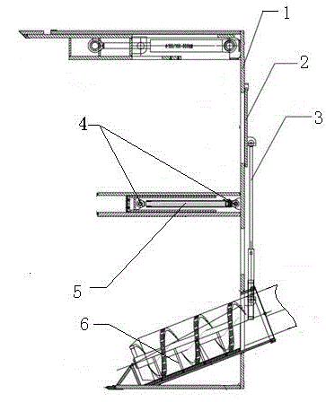
[0014] This embodiment provides a connection structure of the sealing device of the shield machine, which is characterized in that: the connection structure of the sealing device of the shield machine includes a shield machine partition (1), a sealing device partition (2), a hydraulic Cylinder A (3), hydraulic cylinder B (4), observation plate (5), conveyor (6);

[0015] Among them: the sealing device partition (2) and the observation plate (5) of the structure are both hinged with the shield machine partition (1) through the hydraulic cylinder, and the sealing device partition (2) is connected with the hydraulic cylinder A (3). The plate (5) is connected to the hydraulic cylinder B (4), and the shield machine partition (1) and hydraulic cylinder A (3) are connected to the delivery port of the conveyor (6) on the shield machine.

[0016] The observation plate (5) is vertically arranged with the sealing device partition (2) and the shield machine partition (1).

[0017] A hydr...


PUM


Abstract

The invention provides a mechanical connecting structure of a shield machine sealing device. The mechanical connecting structure of the shield machine sealing device is characterized by comprising a shield machine separation plate, a sealing device separation plate, hydraulic cylinders A, hydraulic cylinders B, an observation plate and a conveyor, wherein the sealing device separation plate and the observation plate of the structure are movably hinged to the shield machine separation plate through the hydraulic cylinders; the observation plate is arranged in a way of being vertical to the sealing device separation plate and the shield machine separation plate; the sealing device separation plate is connected with the hydraulic cylinders A; one hydraulic cylinder is arranged at each of two sides of the sealing device separation plate; the observation plate is connected with the hydraulic cylinders B; one hydraulic cylinder is arranged at each of two sides of the observation plate; and the shield machine separation plate and the hydraulic cylinder A are connected onto a conveying opening of the conveyor of a shield machine. The mechanical connecting structure of the shield machine sealing device has the advantages that the balance can be maintained all the time; the stable and effective control is realized; the operation is safe; the production efficiency is high; and the operation risk is reduced to the minimum.

Description

technical field [0001] The invention relates to the field of a novel shield machine mechanical device, and in particular provides a mechanical connection structure of a shield machine sealing device. Background technique [0002] Existing shield machines are generally suitable for various surrounding rocks with a certain self-stabilization ability, low moisture content or no water in the excavation surface, and are suitable for soils such as sand, gravel, consolidated silt, clay and eggs in diluvial layers. When encountering sand and pebble formations with poor self-stability, after conventional excavation disturbs the original formation, sand and pebbles are easy to separate, and then slip and collapse, causing the excavation surface to be unstable, affecting normal excavation, and seriously Sometimes it will cause collapse, which will have a certain impact on the construction and surrounding environment. During the construction of the sand and pebble stratum with poor self...

Claims


Application Information

Patent Timeline
Patent Type & Authority Applications(China)
IPC IPC(8): E21D9/06
Inventor 陈杰
Owner 陈杰
Learn More