Supercharge Your Innovation With Domain-Expert AI Agents!

Material Transfer Valve with Seat Protector

A material conveying valve, protective sleeve technology, applied in valve details, valve device, sliding valve and other directions, can solve the problems of difficult processing, short service life, leakage, etc., to improve service life and sealing performance, easy to manufacture, simple structure Effect

Active Publication Date: 2018-09-25
SICHUAN KENE IND EQUIP MFG
View PDF6 Cites 0 Cited by
  • Summary
  • Abstract
  • Description
  • Claims
  • Application Information

AI Technical Summary

Problems solved by technology

The inner wall of the annular groove is thin, difficult to process, easy to damage and cause leakage, and short service life

Method used


Image

  • Material Transfer Valve with Seat Protector
  • Material Transfer Valve with Seat Protector

Examples


Embodiment 1

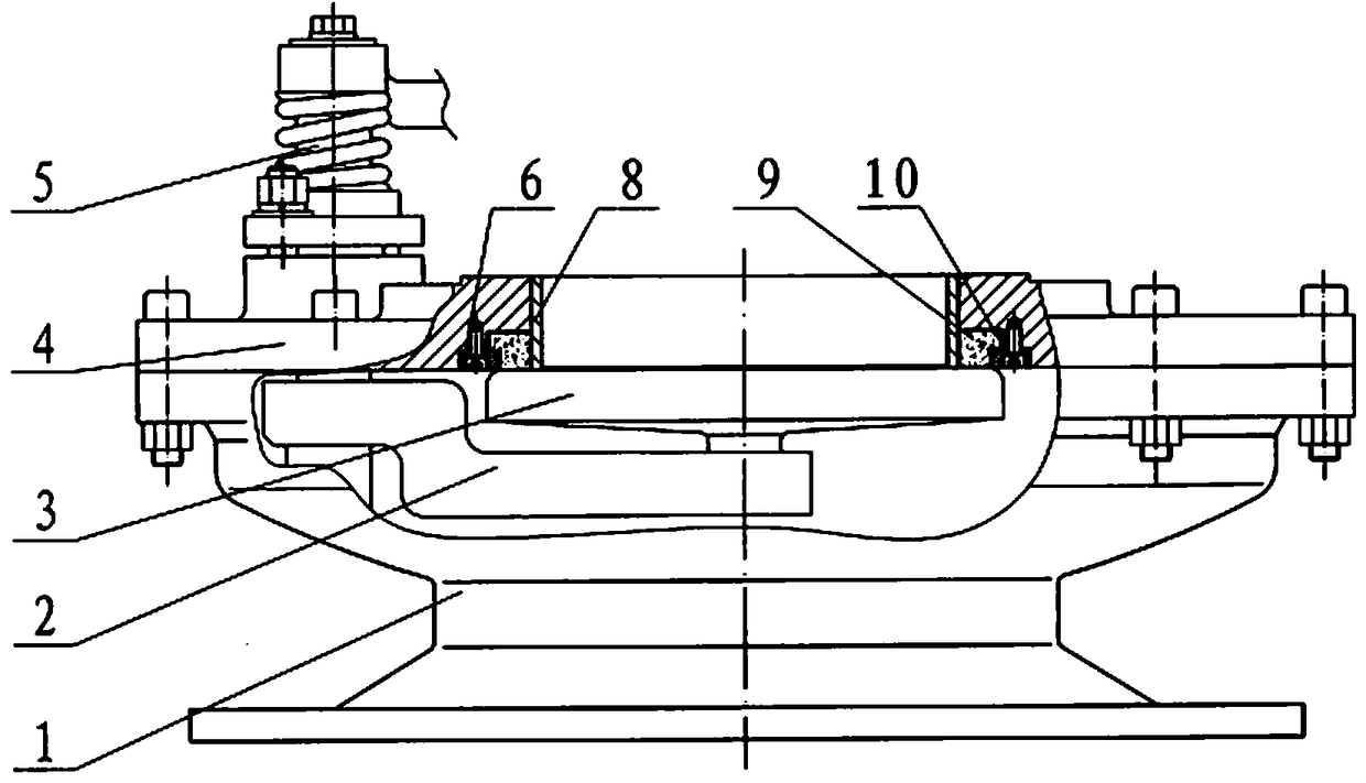
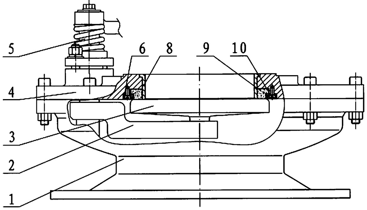
[0014] The material delivery valve with a protective sleeve on the valve seat, the valve body 1 and the valve cover 4 are connected by bolts, the lower end of the rotating shaft 5 is fixedly connected with one end of the rotating arm 2, the other end of the rotating arm is connected with the valve plate 3, and the valve plate and the valve cover The ceramic valve seat 9 on 4 is sealed and fit. The central hole of the valve cover 4 is a straight hole, and its lower end surface has an annular groove. The ceramic valve seat 9 is an L-shaped ring with a wide upper part and a narrower lower part. The groove is statically matched with the ceramic valve seat 9, the lower end surface of the valve cover, the lower end surface of the ceramic valve seat, and the lower end surface of the metal pressure ring 6 are on the same plane, the ceramic valve seat and the annular groove are of the same height, the lower part of the annular groove, the ceramic valve seat 9, the height of the metal pr...

Embodiment 2

[0016] The upper end of the central hole of the valve cover 4 has a step to cooperate with the upper end flange of the steel sleeve 8, which is convenient for the installation, disassembly and positioning of the steel sleeve 8. All the other are identical with embodiment 1.


PUM


Abstract

The invention discloses a material conveying valve with a protective cover on a valve seat, and aims at solving the problems that an existing material conveying valve with an L-shaped protective cover on a valve seat is thin in inner wall of an annular groove, difficult to machine, prone to damage to cause leakage and short in service life. A straight hole serves as a center hole of a valve deck (4), the lower end face of the valve deck (4) is provided with an annular groove, a circular ring of which the cross section is an L shape is adopted as the ceramic valve seat (9), the ceramic valve seat is wide in upper portion and narrow in lower portion, and the annular groove is matched with the ceramic valve seat (9); the lower end face of the valve deck, the lower end face of the ceramic valve seat and the lower end face of a metal press ring (6) are in the same plane, the ceramic valve seat and the annular groove are equal in height, the lower portion of the annular groove, the lower portion of the ceramic valve seat (9) and the metal press ring are equal in height, the outer diameter of the metal press ring is movably matched with the large outer diameter of the lower portion of the annular groove, the inner diameter of the metal press ring is movably matched with the small outer diameter of the lower portion of the ceramic valve seat, the ceramic valve seat is fixedly connected to the valve deck through screws (10) by means of the metal press ring after being contained in the annular groove of the valve deck, a vertically inward open groove is adopted as an annular groove, and a steel sleeve (8) is in stationary fit with the center hole of the valve deck (4) to close the annular groove to enable the annular groove to become a vertical closed groove.

Description

Technical field: [0001] The invention is related to the valves of the fly ash conveying bin pump, the pipeline and the ash storehouse of the thermal power plant, especially related to the material conveying valve. Background technique: [0002] In the existing material conveying valve with a valve cover and a valve seat protective sleeve, the valve body 1 and the valve cover 4 are connected by bolts, the lower end of the rotating shaft 5 is fixedly connected to one end of the rotating arm 2, and the other end of the rotating arm is connected to the valve plate 3. The valve plate is tightly matched with the ceramic valve seat 9 on the valve cover 4. The central hole of the valve cover 4 is a straight hole, and its lower end surface has an annular groove 8 with an L-shaped cross section. The upper bottom of the annular groove is narrow and the lower part is wide. Ceramic valves Seat 9 is a circular ring with an L-shaped cross-section. The upper part of the ceramic valve seat i...

Claims


Application Information

Patent Timeline
Patent Type & Authority Patents(China)
IPC IPC(8): F16K3/06F16K3/30F16K27/08
CPCF16K3/06F16K3/30F16K27/08
Inventor 贺雅成冯缨
Owner SICHUAN KENE IND EQUIP MFG
Features
  • R&D
  • Intellectual Property
  • Life Sciences
  • Materials
  • Tech Scout
  • Unparalleled Data Quality
  • Higher Quality Content
  • 60% Fewer Hallucinations
Learn More