A solar collector system with intelligent water level control
A solar collector and collector technology, applied in the field of solar energy, can solve the problems of low degree of automation of solar collectors, not many researches on intelligent control of collectors, etc., to achieve the best heat exchange effect and improve intelligence Effect
- Summary
- Abstract
- Description
- Claims
- Application Information
AI Technical Summary
Problems solved by technology
Method used
Image
Examples
Embodiment 1
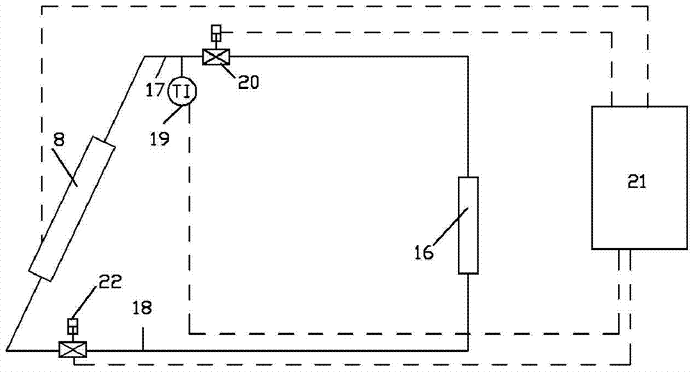
[0091] As an improvement, a temperature sensor is provided in the water tank 8 for measuring the temperature of the water in the water tank 8 . The inlet pipe 18 and the outlet pipe 17 of the water tank 8 are provided with an inlet pipe valve 22 and an outlet pipe valve 20 respectively, and the temperature sensor, the inlet pipe valve 22 and the outlet pipe valve 20 are connected with the central controller 21 for data. The central controller 21 controls the opening and closing and opening degree of the inlet pipe valve 22 and the outlet pipe valve 20 according to the temperature measured by the temperature sensor.
[0092] If the temperature of the water in the water tank 8 measured by the temperature sensor is lower than the lower limit value, then the central controller 21 controls the valves 20 and 22 to close automatically, thereby ensuring that the water in the water tank 8 continues to heat up; When the temperature exceeds the upper limit, the central controller 21 cont...
Embodiment 2
[0099] As an improvement, the central controller 21 ensures that the outlet water temperature in the water tank reaches a constant value by controlling the openings of the valves 20 and 22 . That is, the temperature of the outlet water of the water tank 8 is adjusted by adjusting the flow rate entering the water tank 8 and leaving the water tank 8 .
[0100] An outlet pipe temperature sensor 19 is arranged on the outlet pipeline 17 of the water tank, and the outlet temperature sensor 19 is connected with the data of the central controller 21, and the central controller 21 controls the inlet pipe valve 22 and the outlet pipe valve according to the temperature measured by the temperature sensor 19 20 opening and closing and the size of the opening.
[0101] If the temperature of the water in the outlet pipe 19 measured by the temperature sensor 19 is lower than the lower limit value, the central controller 21 controls the opening of the valve 20 to increase, reducing the opening...
Embodiment 3
[0108] As a further improvement of the second embodiment, the opening and closing of the valves 20 and 22 are controlled by measuring the temperature of the water in the water tank 8 .
[0109] If the temperature of the water in the water tank 8 measured by the temperature sensor 19 is lower than the lower limit value, the central controller 21 controls the opening of the valve 20 to increase, and reduces the opening of the valve 22, so that the water entering the water tank 8 decreases, leaving The water in the water tank 8 increases, thereby reducing the amount of water in the water tank 8 . The temperature of the water in the water tank 8 is increased by reducing the amount of water, thereby increasing the outlet temperature of the water tank 8 . On the contrary, if the temperature of the water in the water tank 8 measured by the temperature sensor 19 is higher than the upper limit value, then the central controller 21 controls the opening of the valve 20 to decrease, and i...
PUM
 Abstract
Description
Claims
Application Information
 - R&D
- Intellectual Property
- Life Sciences
- Materials
- Tech Scout
- Unparalleled Data Quality
- Higher Quality Content
- 60% Fewer Hallucinations
Browse by: Latest US Patents, China's latest patents, Technical Efficacy Thesaurus, Application Domain, Technology Topic, Popular Technical Reports.
© 2025 PatSnap. All rights reserved.Legal|Privacy policy|Modern Slavery Act Transparency Statement|Sitemap|About US| Contact US: help@patsnap.com


