Power generation structure, fabrication method thereof and electronic device

A technology for electronic equipment and power generation units, which is applied to generators/motors, mechanical equipment, power circuits, etc., and can solve problems such as poor battery life and insufficient user experience.

Active Publication Date: 2016-04-06
BOE TECH GRP CO LTD
View PDF4 Cites 9 Cited by
  • Summary
  • Abstract
  • Description
  • Claims
  • Application Information

AI Technical Summary

Problems solved by technology

[0004] However, most of the current smart wearable products have poor battery life and insufficient user experience.

Method used


Image

  • Power generation structure, fabrication method thereof and electronic device
  • Power generation structure, fabrication method thereof and electronic device
  • Power generation structure, fabrication method thereof and electronic device

Examples


Embodiment Construction

[0042] The following will clearly and completely describe the technical solutions in the embodiments of the present invention with reference to the accompanying drawings in the embodiments of the present invention. Obviously, the described embodiments are only some, not all, embodiments of the present invention. Based on the embodiments of the present invention, all other embodiments obtained by persons of ordinary skill in the art without making creative efforts belong to the protection scope of the present invention.

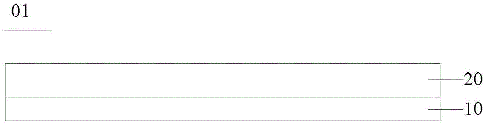
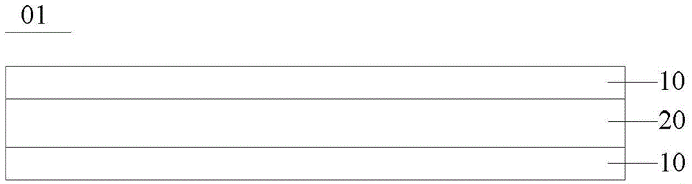
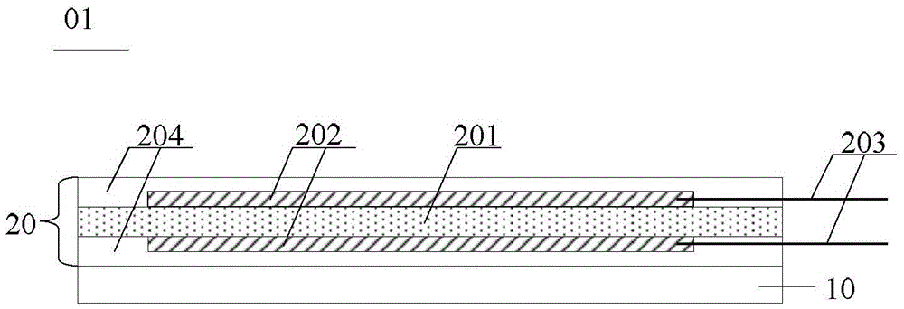
[0043] An embodiment of the present invention provides a power generation structure, such as Figure 1a and Figure 1b , Figure 4a and Figure 4b As shown, the power generation structure 01 includes: a deformation unit 10 and a power generation unit 20; wherein, the deformation unit 10 includes a conductive polymer film layer, and the conductive polymer film layer includes electrolyte ions; the power generation unit 20 is used for mechanical force lower out...


PUM


Abstract

The embodiment of the invention provides a power generation structure, a fabrication method thereof and an electronic device, relating to the field of manufacturing of the electronic device. The cruising ability of the electronic device can be improved by using the power generation structure. The power generation structure comprises a deformation unit and a power generation unit, wherein the deformation unit comprises a conductive polymer film layer, the conductive polymer film layer comprises electrolytic ions, the power generation unit is used for outputting voltage under the action of a mechanical force, and the deformation unit is used for generating the mechanical force on the power generation unit during deformation. The power generation unit is used for a small-sized electronic device.

Description

technical field [0001] The invention relates to the field of electronic equipment manufacturing, in particular to a power generation structure, a preparation method thereof, and electronic equipment. Background technique [0002] At present, the endurance of electronic devices depends on their own batteries. With the miniaturization of electronic devices such as mobile phones and smart wearable products, due to their small size, in order to save space, the volume of their batteries is correspondingly small. As a result, the battery life of current electronic products is poor. [0003] Taking smart wearable products as an example, with the application of smart wearable products, consumers have gradually shifted from functional requirements for smart wearable products to requirements for battery life. [0004] However, most of the current smart wearable products have poor battery life and insufficient user experience. Contents of the invention [0005] Embodiments of the p...

Claims


Application Information

Patent Timeline
IPC IPC(8): H01L41/113H01L41/083H01L41/27
CPCH10N30/30H10N30/50H10N30/05H02N2/18F03G7/0612H10N30/878H10N30/852H10N30/857H10N30/03H10N30/06H10N30/081H10N30/092H10N30/098H10N30/306H10N30/875H10N30/886G04G19/00H02N2/22
Inventor 杨久霞白峰
Owner BOE TECH GRP CO LTD
Why Eureka
Try Eureka