Electromagnetic diaphragm earphone

An earphone and electromagnetic technology, which is applied in the earpiece/earphone accessories, etc., can solve the problems of sound distortion and uneven force on the diaphragm surface, so as to optimize the sound quality, ensure high fidelity, and improve the audio progress

Inactive Publication Date: 2016-04-06
N 隋摩迪伊
View PDF3 Cites 1 Cited by
  • Summary
  • Abstract
  • Description
  • Claims
  • Application Information

AI Technical Summary

Problems solved by technology

[0008] However, in the prior art, planar electromagnetic diaphragm technology is used in earphones, and the push or pull force caused by electromagnetic induction is often too concentrated on a specific area of ​​the diaphragm, such as the center of the cone surface, causing the diaphragm surface to be stressed Uneven, will cause a high degree of sound distortion

Method used


Image

  • Electromagnetic diaphragm earphone
  • Electromagnetic diaphragm earphone
  • Electromagnetic diaphragm earphone

Examples


Embodiment Construction

[0025] In the following, the same reference numerals refer to the same elements.

[0026] As mentioned above, the present invention aims to provide an electromagnetic diaphragm earphone, and strives to greatly improve the sound effect of the earphone without increasing the cost.

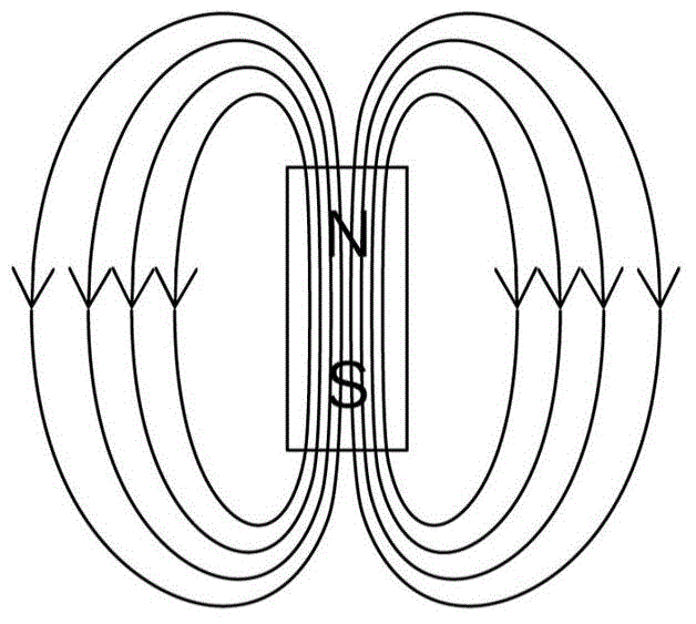
[0027] The electromagnetic diaphragm earphone provided by the present invention includes a magnet array, a conductive link, and a diaphragm to which the conductive link is attached. The diaphragm is pushed / pulled to move by inductive interaction between the conductive link and the magnet array.

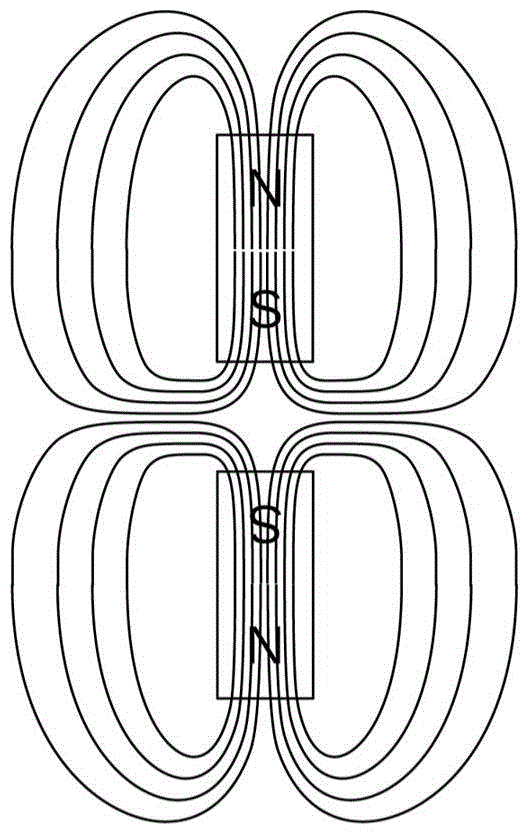
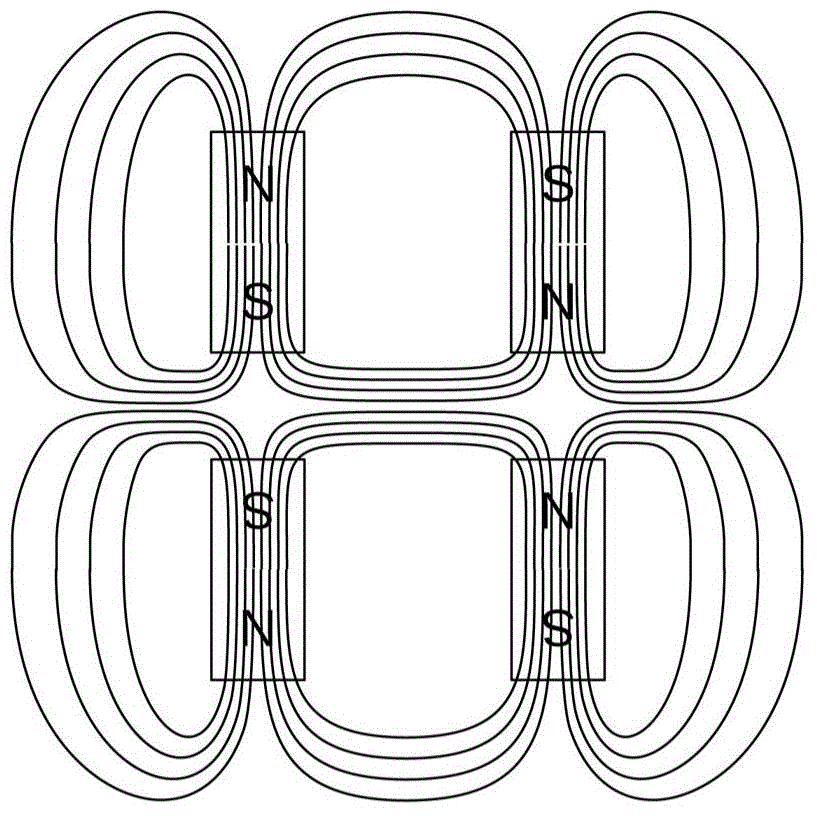
[0028] The magnet array can be a single array or a double array facing each other. For convenience of description, a single-array magnet array is firstly introduced.

[0029] Such as figure 2 As shown, the magnet array 100 forms a matrix form, that is, each magnet has two directly adjacent magnets in the horizontal and vertical directions of the matrix, so in the magnet array, except for the magnets at t...


PUM


Abstract

The invention provides an electromagnetic diaphragm earphone comprising a magnet array, a diaphragm and a conductive link which is adhered on the diaphragm. The shape of the magnet array is a magnet matrix. The diaphragm faces the magnet array. The magnetic pole, which faces the diaphragm, of each magnet is opposite to the magnetic pole, which faces the diaphragm, of four magnets directly adjacent to the magnet in polarity. The conductive link comprises multiple broken wire segments which are formed by one straight wire through bending and connected in an end-to-end way. Observing from the diaphragm to the array, the conductive link firstly extends along the first partial diagonal of the matrix and extends to the edge of the matrix and then reversely turns back to extend along the next partial diagonal so that the conductive link extends until it extends to leave the matrix from the last partial diagonal. In the extension path of the link, a bending part composed of two broken wire segments is formed for the magnet when the conductive link passes one magnet, and the magnet is half-surrounded by the bending part so that thrust/suction obtained through induction of a magnetic field is ensured to be uniformly distributed on the overall surface of the diaphragm to the largest extent, and high fidelity of the sound effect of the earphone can be ensured.

Description

technical field [0001] The invention relates to an electromagnetic diaphragm earphone. Background technique [0002] At present, there are a considerable number of earphone products on the market using planar electromagnetic diaphragm technology (PlanarMagneticTechnology). This technology will be briefly introduced below. [0003] As we all know, in a magnet, the magnetic field lines are drawn from the north pole (N pole) to the south pole (S pole) outside the magnet, and from the south pole to the north pole inside the magnet, which constitutes the magnetic field of the magnet, such as Figure 1a shown. [0004] When two magnets are placed facing each other at the same level (for example, the south pole of one magnet faces the south pole of the other magnet), the respective magnetic fields of the two magnets will squeeze each other, such as Figure 1b shown. [0005] And when four magnets such as Figure 1c When placed as shown, in two side by side magnets, the south po...

Claims


Application Information

Patent Timeline
Patent Type & Authority Applications(China)
IPC IPC(8): H04R1/10
Inventor N·隋摩迪伊
Owner N 隋摩迪伊
Why Eureka
Try Eureka