An air fragrance machine

A fragrant machine and air technology, applied in the direction of vaporized substances and atomized substances, can solve the problems of large heat loss, easy blockage, poor thermal conductivity, etc., to achieve the effect of small heat loss, cost reduction, and improvement of breathing environment

A fragrant machine and air technology, applied in the direction of vaporized substances and atomized substances, can solve the problems of large heat loss, easy blockage, poor thermal conductivity, etc., to achieve the effect of small heat loss, cost reduction, and improvement of breathing environment

CN105477668BInactive Publication Date: 2018-08-07胡积献 +1

Image

  • An air fragrance machine
  • An air fragrance machine
  • An air fragrance machine

Examples


Embodiment 2

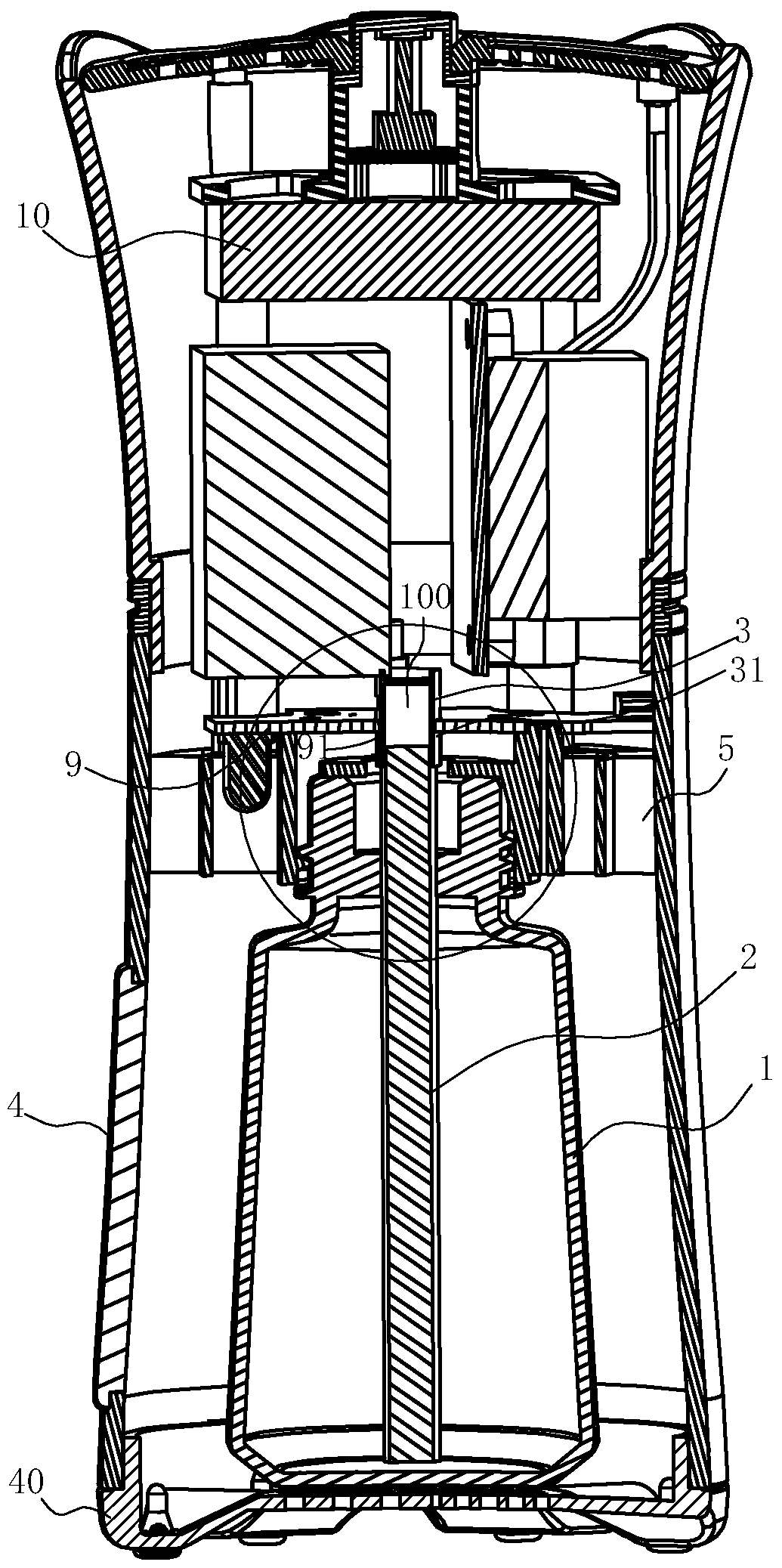
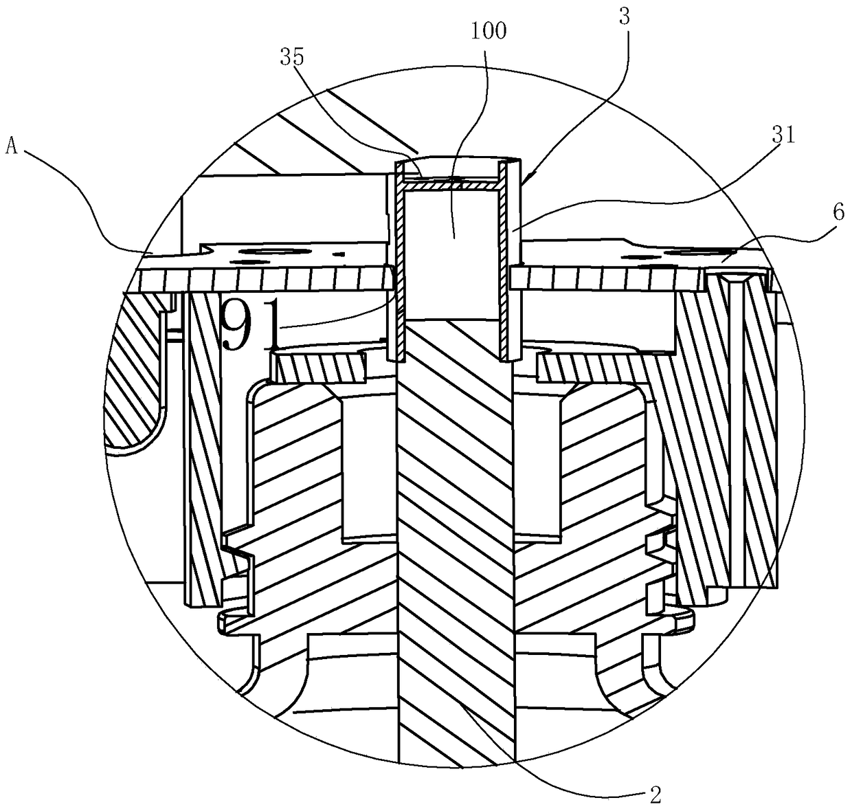
[0041] The structure is the same as that of Embodiment 1, the difference is that the convex wall 31 of the catalytic core head 3 has a first bump 33 and a second bump 34, and the fixing device 7 includes a first pillar 71 and a first pillar 71 that are compatible with the corresponding bumps. The second pillar 72, and the first pillar 71 and the second pillar 72 are respectively provided with a first positioning buckle 711 and a second positioning buckle 721, and the first protrusion 33 is clamped on the first positioning buckle 711 and the second protrusion 34 is set in the state of the second positioning buckle 721, the catalytic core head 3 can be fixed on the circuit board 9. Utilize the first protruding block 33 and the second protruding block 34 that its peripheral wall has, and the first positioning buckle 711 and the second positioning buckle 721 that are fixed on the first support 71 and the second support 72 in the circuit board 9 of the bracket 5 are engaged. Set, t...

Embodiment 3

[0043] The structure is the same as that of Embodiment 1, the difference is that the fixing device 7 is a mounting seat 76 arranged in the mounting hole 91 of the circuit board 9, the mounting seat 76 has an opening 761 whose diameter gradually increases from top to bottom, and in the catalytic core The head 3 is provided with an elastic O-ring 8 that fits the opening 761. When the catalytic core head 3 moves up and the mounting seat 76 contacts the elastic O-ring 8, the opening 761 can press the elastic O-ring 8 so that the The elastic O-ring 8 is positioned on the mounting seat 76 together with the catalytic core head 3, and other structures refer to Embodiment 1, such as Figure 10 shown.

Embodiment 4

[0045] The structure is the same as that of Embodiment 1, the difference is that the fixing device 7 includes a third pillar 74, and the third pillar 74 is provided with a hoop 75 capable of positioning the catalytic core head 3, and the hoop 75 can be supported by two elastic claws. 80 structure, the catalytic core head 3 can be placed in it in the state where the two elastic claws are opened, and the catalytic core head 3 is fastened in the closed state. For other structures, refer to Example 1, such as Figure 11 shown.


PUM


Abstract

The invention relates to an air perfuming machine, comprising a shell, wherein an essential oil bottle, a mandril and a catalysis bud head are arranged in the shell; the air perfuming machine is characterized in that a support in detachable connection with the catalysis bud head is arranged in the shell, the support is provided with a circuit board, the circuit board is provided with a mounting hole for the catalysis bud head to pass through, the catalysis bud head comprises a cover body, the periphery of the cover body is provided with a containing cavity which is defined by a convex wall, and capable of containing the mandril, and the cover body is provided with at least one through hole at a position opposite to the end part of the mandril. Compared with the prior art, the air perfuming machine has the advantages that the catalysis bud head is in detachable connection with the support for further achieving the aim of directly replacing the essential oil bottle; besides, the support is provided with the circuit board, the circuit board is provided with the mounting hole for the catalysis bud head to pass through, and the catalysis bud head is provided with the containing cavity capable of containing the mandril, and the containing cavity can ensure that all heat of the catalysis bud head is used for heating the mandril, so the heat loss is small, and an essential oil volatilization rate enables a temperature to quickly rise to 100 DEG C within a short time of 30s-1min.

Description

technical field [0001] The invention relates to an air fragrance purifier with a catalytic core head. Background technique [0002] Aromatherapy essential oil is a kind of fragrant and volatile plant essential oil made by extracting specific kinds of plants through special methods. Plant essential oil is the essence of extracted plant ingredients. It not only has a pleasant aromatic smell, but also has the characteristics of high volatility, small molecules, and can be quickly absorbed by the human body. It also has extremely high medicinal value, whether it is in maintenance It has a certain effect on skin, balancing internal functions and alleviating unfavorable mental emotions. [0003] Aromatherapy products have been in the market for more than ten years. Although the concept is accepted by the general public and the products are also loved by many people, there are still some deficiencies in the structure of the existing products and the way of volatilization of essent...

Claims


Application Information

Patent Timeline
07 Aug 2018
Publication
CN105477668B
IPC
A61L9/03; A61L9/14
CPC
A61L9/03; A61L9/14
Inventors
胡积献