High-rise-building safe escaping device

An escape device and building technology, applied in life-saving equipment, building rescue, etc., can solve the problems of inconvenient carrying, high manufacturing cost, heavy weight, etc., and achieve the effects of simple structure, shortened escape time, and light weight

Inactive Publication Date: 2016-04-13
白云
View PDF11 Cites 2 Cited by
  • Summary
  • Abstract
  • Description
  • Claims
  • Application Information

AI Technical Summary

Problems solved by technology

[0002] High-rise fires happen from time to time, and most of the materials used for house decoration are not fireproof materials. Once a fire breaks out, it will cause a horrible and tragic scene in an instant. The consequences of jumping directly from a tall building will be unimaginable, so various emergency escape devices have emerged as the times require
However, there are many deficiencies in the structural scheme of the current escape device. One is to penetrate the escape device from one end of the escape rope. In use, the escape device cannot be installed or removed from the escape rope conveniently and quickly, so the precious best escape time is missed; the second is that most of the buffer braking mechanisms use rubber brake pads and brake pads, which are easy to slip when sliding at high speed. Heat generation, rubber brake pads or brake pads are easy to deform, hug, or even damage, which has potential safety hazards; the third is that the structure is more complicated, heavier, and inconvenient to carry. Some use gear structures, and some use turbine structures, etc. The complex volume is large and heavy, which makes it inconvenient to install, use and carry. The gear and turbine structure is also easy to wear and tear, which brings safety hazards, and the manufacturing cost is also high.

Method used


Image

  • High-rise-building safe escaping device
  • High-rise-building safe escaping device
  • High-rise-building safe escaping device

Examples


Embodiment Construction

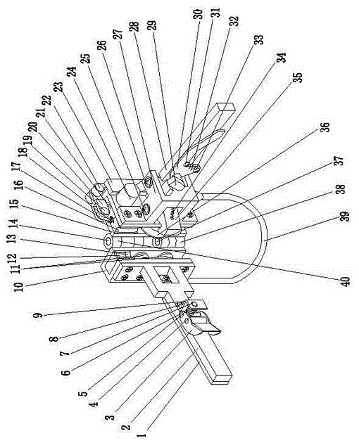
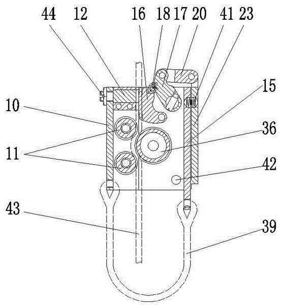
[0020] The specific embodiment of the present invention is, with reference to figure 1 , figure 2 , including a pulley frame, a handle, a lock assembly, a slow-down assembly, an escape rope and a sling cover, the pulley frame includes a fixed pulley frame, a movable pulley frame, an upper folding shaft, and a lower folding shaft, wherein the fixed Pulley frame 10 and movable pulley frame 15 are hinged by upper hinge shaft 14 and lower hinge shaft 37, and described handle comprises fixed pulley frame handle 2, movable pulley frame handle 28, movable pulley frame handle seat 27, and the fixed pulley Frame handle 2 is connected with the said pulley frame 10, and said movable pulley frame handle seat 27 is connected with said movable pulley frame 15, and said movable pulley frame handle 28 is hinged with said movable pulley frame handle seat 27 by pin 26 , the lock assembly includes a lock 35, a pin 25, an extension spring 34 and a lock lock assembly, the lock 35 is hinged with ...


PUM


Abstract

The invention discloses a high-rise-building safe escaping device. The high-rise-building safe escaping device comprises a pulley yoke, a grabbing handle, a lock catch assembly, a slow descending assembly, an escaping rope and a sling sleeve. The pulley yoke comprises a fixed pulley yoke body, a movable pulley yoke body, an upper hinge shaft and a lower hinge shaft. The grabbing handle comprises a fixed pulley yoke grabbing handle body, a movable pulley yoke grabbing handle body and a movable pulley yoke grabbing handle base. The lock catch assembly comprises a lock catch, a pin shaft, a tension spring and a lock catch ejector locking assembly. The lock catch ejector locking assembly comprises an ejector rod and an ejector rod locking assembly. The slow descending assembly comprises a pulley block and a brake mechanism. The pulley block comprises two fixed pulleys and a movable pulley. The brake mechanism comprises a linkage assembly and a limiting assembly. The linkage assembly comprises a brake frame, a connecting rod, a shifting block, a shifting crank arm, fixed clamping blocks and a movable clamping block. The high-rise-building safe escaping device has the beneficial effects that slow downward sliding and braking are achieved by tensioning the pulleys and the brake mechanism; and in addition, the escaping device can be conveniently and rapidly installed on the escaping rope to carry out continuous downward sliding, escaping time is shortened, and the buffering brake mechanism is safe and reliable.

Description

technical field [0001] The invention relates to the technical field of safety equipment, in particular to a safety escape device for high-rise buildings. Background technique [0002] High-rise fires happen from time to time, and most of the materials used for house decoration are not fireproof materials. Once a fire breaks out, it will cause a horrible and tragic scene in an instant. The consequences of jumping directly from tall buildings will be unimaginable, so various emergency escape devices have emerged as the times require. However, there are many deficiencies in the structural scheme of the current escape device. One is to penetrate the escape device from one end of the escape rope. In use, the escape device cannot be installed or removed from the escape rope conveniently and quickly, so the precious best escape time is missed; the second is that most of the buffer braking mechanisms use rubber brake pads and brake pads, which are easy to slip when sliding at high ...

Claims


Application Information

Patent Timeline
Patent Type & Authority Applications(China)
IPC IPC(8): A62B1/10A62B1/18
Inventor 白云白玉富
Owner 白云
Why Eureka
Try Eureka