Isolating switch of inflatable switch cabinet

A technology of isolating switch and switchgear, which is applied in the direction of air switch components, switchgear setting, switchgear, etc., can solve the problems of low work efficiency and slow installation speed, achieve fast installation speed, improve heat dissipation effect, and extend service life Effect of Life and Replacement Periods

Pending Publication Date: 2021-07-30
QUANZHOU SEVENSTARS ELECTRIC
View PDF6 Cites 0 Cited by
  • Summary
  • Abstract
  • Description
  • Claims
  • Application Information

AI Technical Summary

Problems solved by technology

The existing isolating switch body is generally installed in the switch cabinet by bolts, the installation speed is slow and the work efficiency is low

Method used


Image

  • Isolating switch of inflatable switch cabinet
  • Isolating switch of inflatable switch cabinet
  • Isolating switch of inflatable switch cabinet

Examples


Embodiment 1

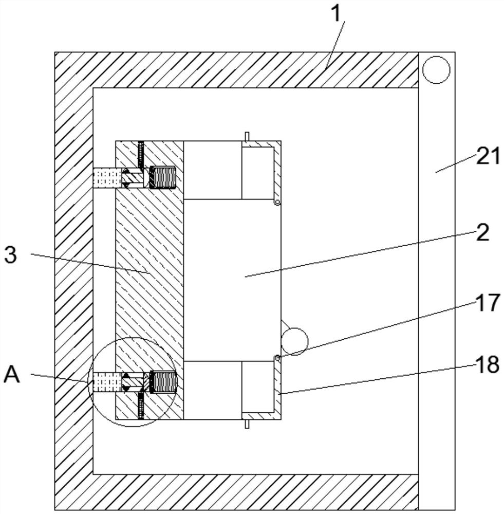
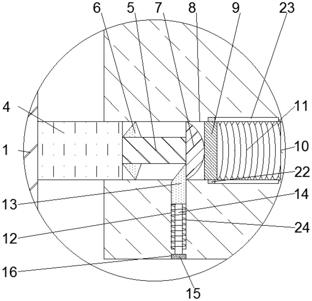
[0024] see Figure 1-3 , according to an embodiment of the present invention, an isolating switch of an inflatable switchgear, comprising a switchgear 1, the isolating switch body 2 is installed in the switchgear 1, and the isolating switch body 2 is fixed on a side close to the switchgear 1 A mounting plate 3 is connected, and the four corners of the switch cabinet 1 close to the mounting plate 3 are fixedly connected with a fixed block 4, and the side of the fixed block 4 away from the switch cabinet 1 is fixedly connected with a slide bar 5, so The outer surface of the slide bar 5 is slidably connected with a slider 6, and the end of the slide bar 5 away from the fixed block 4 is fixedly connected with a semicircle block 7, and the mounting plate 3 is provided with a card near the semicircle block 7. Connecting hole 8, the clamping hole 8 is adapted to the semicircular block 7 and the fixed block 4, one side of the clamping hole 8 is provided with an extrusion plate 9, and ...

Embodiment 2

[0026] see Figure 1-3 , the buckle mechanism includes a cavity two 12, a block 13, a push rod 14, a limit block 15 and a spring two 24, and the mounting plate 3 is provided with a cavity two 12 near the semicircular block 7, and the A block 13 is slidably connected to the cavity two 12, and the end of the block 13 away from the semicircular block 7 is fixedly connected with a push rod 14, and the end of the push rod 14 away from the block 13 passes through the mounting plate And extend to the limit block 15, the limit block 15 is fixedly connected with the push rod 14, the outer surface of the push rod 14 is provided with a spring two 24, the clamp block 13 and the semicircular block 7 Matching, the clamping block 13 is matched with the slider one 6, and the mounting plate 3 is provided with a groove 16 close to the limiting block 15, and the limiting block 15 and the groove 16 Compatible, stable installation, not easy to fall.

Embodiment 3

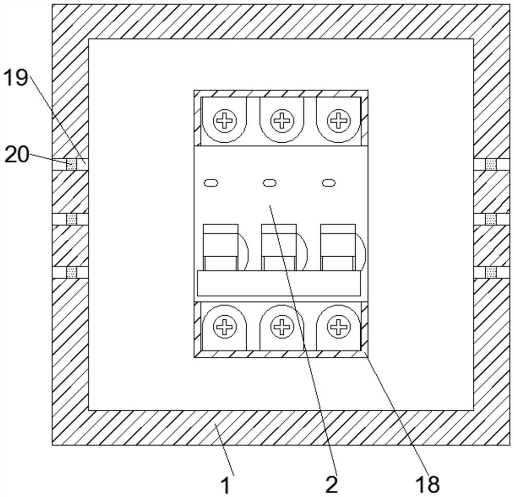
[0028] see Figure 1-3 , the two ends of the isolating switch body 2 away from the mounting plate 3 are movably connected with a rotating shaft 17, and the outer surface of the rotating shaft 17 is fixedly connected with a protective shell 18, which isolates the wiring bolts on the isolating switch body 2 To prevent accidental electric shock, the two sides of the switch cabinet 1 are provided with heat dissipation holes 19, and the heat dissipation holes 19 are fixedly connected with a dust-proof net 20, which improves the heat dissipation effect of the isolating switch body 2 in the switch cabinet 1, The service life and replacement cycle of the isolating switch body 2 are extended, the cost is reduced and the dustproof effect is good. One side of the switch cabinet 1 is hinged with a protective cover 21 to protect the isolating switch body 2. The extrusion plate 9 Two sliders 22 are fixedly connected at both ends, and a slide groove 23 is opened in the first cavity 10 close ...


PUM


Abstract

The invention discloses an isolation switch of an inflatable switch cabinet, which comprises a switch cabinet, an isolation switch body is mounted in the switch cabinet, a mounting plate is fixedly connected to one side, close to the switch cabinet, of the isolation switch body, and fixing blocks are fixedly connected to four corners of one side, close to the mounting plate, of the switch cabinet. The side, away from the switch cabinet, of the fixing block is fixedly connected with a sliding rod, the outer surface of the sliding rod is slidably connected with a first sliding block, the end, away from the fixing block, of the sliding rod is fixedly connected with a semicircular block, a clamping hole is formed in the position, close to the semicircular block, of the mounting plate, and the clamping hole is matched with the semicircular block and the fixing block. An extrusion plate is arranged on one side of the clamping hole, and a first cavity is formed in the side, away from the clamping hole, of the extrusion plate. The beneficial effects are that the installation process of the isolation switch body in the switch cabinet is simplified, and the working efficiency is improved.

Description

technical field [0001] The invention relates to the field of high-voltage anti-electricity devices, in particular to an isolating switch of an inflatable switch cabinet. Background technique [0002] Isolating switch is the most widely used electrical appliance in high-voltage switchgear. Its working principle and structure are relatively simple. The impact is relatively large. The main function of the disconnector is to establish a reliable insulation gap after opening, and separate the settings or lines that need to be repaired from the power supply with an obvious disconnection point to ensure the safety of maintenance personnel and equipment. The existing isolating switch body is generally installed in the switch cabinet by bolts, which is slow in installation speed and low in work efficiency. [0003] Aiming at the problems in the related technologies, no effective solution has been proposed yet. Contents of the invention [0004] The object of the present invention...

Claims


Application Information

Patent Timeline
Patent Type & Authority Applications(China)
IPC IPC(8): H02B1/04H02B1/56H02B1/28H02B1/30H02B1/32H02B13/035H01H31/02
CPCH02B1/04H02B1/565H02B1/28H02B1/306H02B1/32H02B13/035H01H31/02
Inventor 黄春铃陈金威
Owner QUANZHOU SEVENSTARS ELECTRIC
Why Eureka
Try Eureka