Less effort speed changer

An accelerator and force technology, which is applied in the direction of vehicle gearbox, wheel transmission, transportation and packaging, can solve the problems of labor-saving and unsafe, and achieve the effect of simple structure.

Inactive Publication Date: 2016-04-13
杨小全
View PDF5 Cites 0 Cited by
  • Summary
  • Abstract
  • Description
  • Claims
  • Application Information

AI Technical Summary

Problems solved by technology

[0002] In the existing riding tools, when accelerating or applying force to the roller, it usually uses its own weight to make it run quickly, such as riding a tricycle or bicycle, which is very laborious and not safe.
In tricycles, bicycles and other means of transportation, a large gear drives the pinion to rotate, and then the pinion drives the wheel to rotate. Its structure is simple, but it cannot achieve the purpose of saving labor.

Method used


Image

  • Less effort speed changer
  • Less effort speed changer
  • Less effort speed changer

Examples


Embodiment Construction

[0027] The present invention will be further described below in conjunction with accompanying drawing by embodiment:

[0028] preferred embodiment

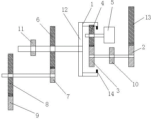
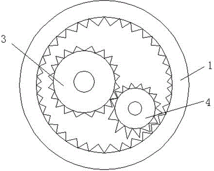
[0029] Such as figure 1 As shown, the present invention achieves the purpose of labor saving and speed change through the connection and driving of each gear, and specifically includes a ring structure with an internal gear, that is, an annular internal gear, and two external gears are arranged inside it, that is, an external gear-one It meshes with external gear 2, external gear 1 and external gear 2, wherein external gear 1 is connected with external pinion 1 and rotates synchronously, and external gear 1 is driven by a power device. The power device here can be driven by manpower or Mechanical drive (including electric drive, wind drive, etc.), the pinion one drives the outer gear one to rotate synchronously, and then drives the second outer gear to rotate, the second outer gear meshes with the annular inner gear to drive the ...


PUM


Abstract

The invention relates to a less effort speed changer, and refers to a less effort device capable of accelerating and decelerating; the technical scheme is that a pressure device is arranged, so besides engaging acting force between an external gear 2 and an annular internal gear, a rotating acting force is also applied between the two, so rotation can be more labor saving; a main gear 1 can synchronously rotate with the annular internal gear; different drive relations and diameters are arranged between the main gear 1 and a pinion 2 and between a main gear 2 and a pinion 3; if the main gear 1 rotate for one circle, the rotating lap speed of the pinion 3 can be greatly enlarged or decreased; when the speed changes, the annular internal gear uses less power force. The speed changer uses a lever principle to continually add acting force in the rotating direction, thus saving labor; the gears are arranged, so speed can be fast changed under same power force.

Description

technical field [0001] The invention relates to a device that saves labor and can accelerate or decelerate. technical background [0002] In the existing riding tools, when accelerating or exerting force on the roller, it usually uses its own weight to make it run quickly, such as riding a tricycle or bicycle, which is very laborious and unsafe. In tricycles or bicycles and other means of transport, its operation is all to drive the pinion to rotate through a large gear, and then the pinion drives the wheel to rotate. Its structure is simple, but it cannot achieve the purpose of labor saving. Contents of the invention [0003] The purpose of the present invention is to solve the problems of the prior art and provide a labor-saving transmission that can both accelerate or decelerate. The accelerator continuously adds force in the direction of rotation through the principle of leverage to achieve the purpose of labor-saving, and through the gear The unique design enables it...

Claims


Application Information

Patent Timeline
Patent Type & Authority Applications(China)
IPC IPC(8): B62M11/04
Inventor 杨小全
Owner 杨小全
Why Eureka
Try Eureka