Cement conveying system
A conveying system and cement technology, applied in the direction of conveyors, transportation and packaging, mixers, etc., can solve the problems of low mixing efficiency, prone to system occurrence, and affecting work efficiency, etc., and achieve high mixing efficiency, convenient use, and simple structure Effect
- Summary
- Abstract
- Description
- Claims
- Application Information
AI Technical Summary
Problems solved by technology
Method used
Image

Examples
Embodiment Construction
[0013] The present invention will be further described below in conjunction with the accompanying drawings.
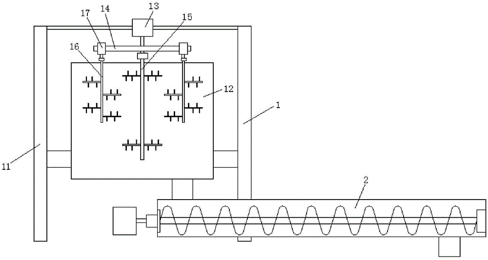
[0014] Such as figure 1 As shown, a cement conveying system of the present invention includes a stirring device 1 and a screw feeder 2 , and the discharge end of the stirring device 1 communicates with the feeding port of the screw feeder 2 .
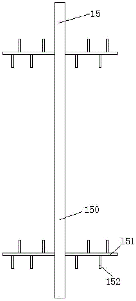
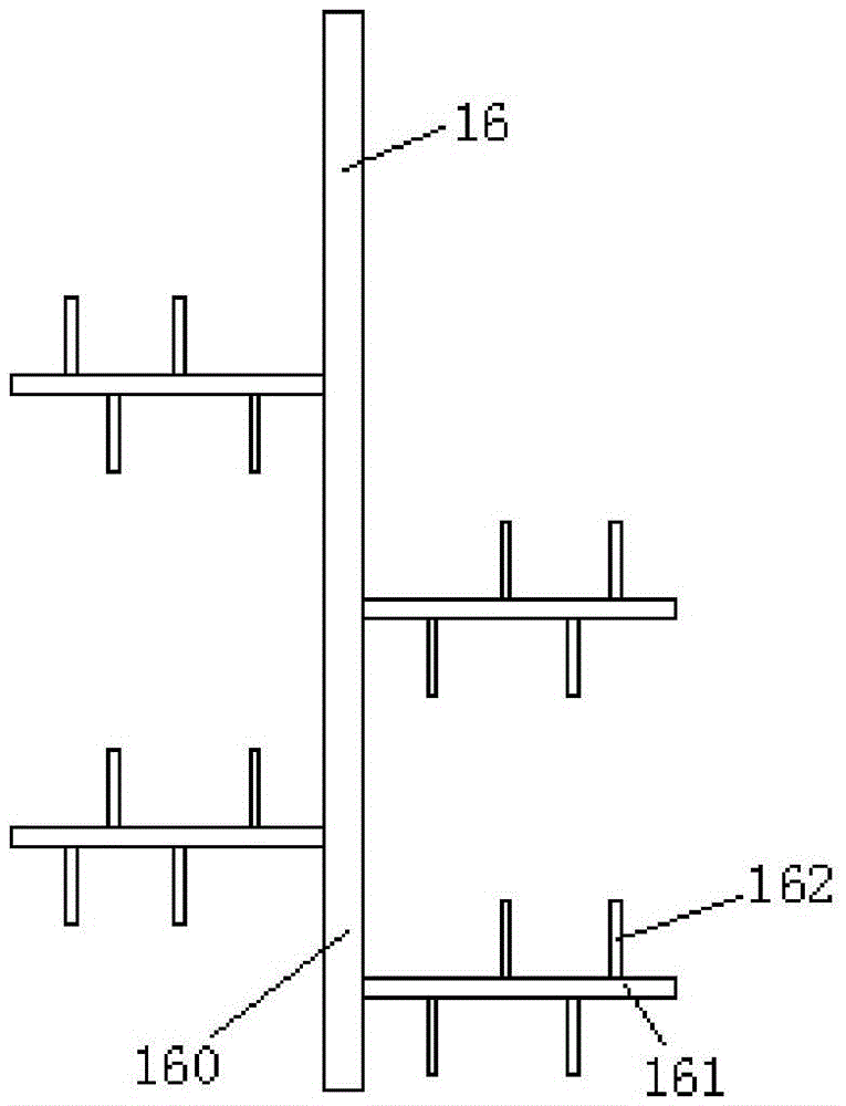
[0015] The stirring device 1 comprises a support 11, a mixing bucket 12, a first motor 13, a cross bar 14, a first spoiler shaft 15, a second spoiler shaft 16 and a second motor 17, and the mixing bucket 12 and the first motor 13 are all fixedly connected On the bracket 11, the rotating shaft of the first motor 13 is fixedly connected to the crossbar 14, two second motors 17 are symmetrically fixedly connected to both ends of the crossbar 14, a first spoiler shaft 15 and two second spoiler shafts The shafts 16 are respectively rotated and installed in the mixing tank 12, and the upper end of the first spoiler shaft 15 extends o...
PUM
 Abstract
Description
Claims
Application Information
 - Generate Ideas
- Intellectual Property
- Life Sciences
- Materials
- Tech Scout
- Unparalleled Data Quality
- Higher Quality Content
- 60% Fewer Hallucinations
Browse by: Latest US Patents, China's latest patents, Technical Efficacy Thesaurus, Application Domain, Technology Topic, Popular Technical Reports.
© 2025 PatSnap. All rights reserved.Legal|Privacy policy|Modern Slavery Act Transparency Statement|Sitemap|About US| Contact US: help@patsnap.com