
Clamping part for novel optical fiber preforms

An optical fiber preform and clamping part technology, which is applied in the field of clamping parts for new optical fiber preforms, can solve problems such as jumping out, swaying, and processing difficulty of optical fiber preforms, and achieves the effect of satisfying positioning and clamping.

Inactive Publication Date: 2016-04-13
SUZHOU WOSEN YOUJIN ELECTRONICS TECH CO LTD
View PDF4 Cites 0 Cited by
  • Summary
  • Abstract
  • Description
  • Claims
  • Application Information

AI Technical Summary

Problems solved by technology

There are following disadvantages in the mode that adopts earlier at present: 1, owing to have used the eccentric ring that has lock hole, thereby need to make the end of optical fiber preform tail handle form a ball head that can be limited by lock hole, so the processing of optical fiber preform 2. Because the optical fiber preform is hung on the optical fiber preform limiting mechanism in an eccentric state, that is to say, the longitudinal center of the optical fiber preform is not consistent with the longitudinal center of the quartz hanging rod, and because the optical fiber preform The ball head at the end of the tail handle is in an unfixed free state, so it is unavoidable to wobble during the process of drawing the optical fiber, and there is even the risk of accidents caused by the ball head jumping out of the opening slot that passes through the lock hole

Method used


Image

  • Clamping part for novel optical fiber preforms

Examples


Embodiment Construction

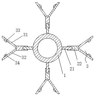
[0013] A new type of clamping part for optical fiber preform of the present invention, the clamping part is arranged on the vertical rod installed vertically in the suspension device, including the installation ring 1 fixedly arranged on the vertical rod, connected with the installation ring 1 and installed along the A number of ribs distributed in the radial direction of the ring 1, a positioning ring 3 arranged at the end of the ribs away from the installation ring 1, the side part of the optical fiber preform is placed in the positioning ring 3, and the ribs are formed by the first rib 21 connected to the installation ring 1 It is composed of the second rib 22 connected with the positioning ring 3 , and the second rib 22 is screwed on the first rib 21 . By adopting the above-mentioned structure, the rib adopts the method of screwing the first rib and the second rib, and the distance between the positioning ring 3 and the center of the mounting ring 1 is changed by changing t...


PUM


Abstract

The invention discloses a clamping part for novel optical fiber preforms. The clamping part is characterized in that the clamping part is arranged on a vertical rod vertically arranged in a suspension device and comprises a mounting ring fixedly arranged on the vertical rod, a plurality of rib plates connected with the mounting ring and distributed in the radial direction of the mounting ring, and positioning rings arranged at the ends, far from the mounting ring, of the rib plates; the side surface parts of the optical fiber preforms are arranged in the positioning rings; the rib plates are composed of first rib plates connected with the mounting ring and second rib plates connected with the positioning rings; the second rib plates are arranged on the first rib plates in a screw-thread fit manner. With the adoption of the structure, the rib plates adopts the manner that the first rib plates are in screw-thread fit with the second rib plates, the centre distances between the positioning rings and the mounting ring can be changed through changing the screw-thread fit lengths of the first rib plates and the second rib plates, so that the effect of telescopic adjustment is realized and thus positioning and clamping requirements of the optical fiber preforms of different specifications and diameters are met.

Description

technical field [0001] The invention relates to a novel clamping part for an optical fiber preform, in particular to a compact and scalable novel clamping part for an optical fiber preform. Background technique [0002] Optical fiber preform is the raw material for manufacturing quartz series optical fiber, specifically, it is a prefabricated rod used to draw optical fiber, usually sintered from silica granular material. As known in the industry, in the process of drawing an optical fiber from a prefabricated rod, that is, an optical fiber preform, it is necessary to suspend and fix the prefabricated rod on a suspension device in a suspended and fixed manner. There are following disadvantages in the mode that adopts earlier at present: 1, owing to have used the eccentric ring that has lock hole, thereby need to make the end of optical fiber preform tail handle form a ball head that can be limited by lock hole, so the processing of optical fiber preform 2. Because the optica...

Claims


Application Information

Patent Timeline
Patent Type & Authority Applications(China)
IPC IPC(8): C03B37/03
CPCC03B37/03
Inventor 蒋培珍
Owner SUZHOU WOSEN YOUJIN ELECTRONICS TECH CO LTD
Learn More