
Construction Method for Installing the Top Valve Box of Large Blast Furnace

A construction method and valve box technology, applied to blast furnaces, blast furnace details, furnaces, etc., can solve problems such as large labor input, long installation time, and low safety, and achieve high safety, overcome errors, and improve installation accuracy.

Active Publication Date: 2017-11-10
CHINA FIRST METALLURGICAL GROUP
View PDF4 Cites 0 Cited by
  • Summary
  • Abstract
  • Description
  • Claims
  • Application Information

AI Technical Summary

Problems solved by technology

[0005] The second method is to install the four blind flanges with the bottom flange of the valve box first, then hoist the valve box to the pillar for alignment and then weld the flanges. This method has the difficulty of installing the valve box in place, and its blind The center, elevation, and relative position between the flange and the four pillars are not easy to determine, which affects the installation accuracy of the lower hopper, etc. There are problems such as long installation time, more labor, and large cranes that cannot be quickly unhooked.
Causes an increase in machinery, labor, materials, costs, high risk of hoisting, low safety during operation, and unguaranteed construction period, etc.

Method used


Image

  • Construction Method for Installing the Top Valve Box of Large Blast Furnace
  • Construction Method for Installing the Top Valve Box of Large Blast Furnace
  • Construction Method for Installing the Top Valve Box of Large Blast Furnace

Examples


Embodiment Construction

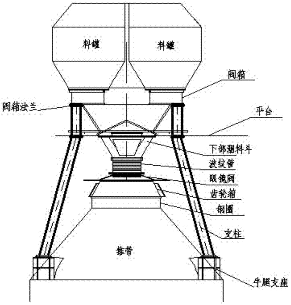
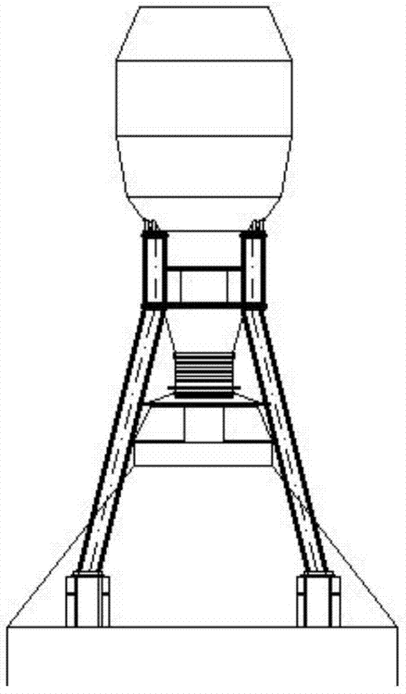
[0043] For a better understanding of the present invention, the inventive method will be further described below in conjunction with the accompanying drawings, see Figure 1 to Figure 11 , the installation and construction method of the large-scale blast furnace roof valve box of the present invention, comprising the following steps:

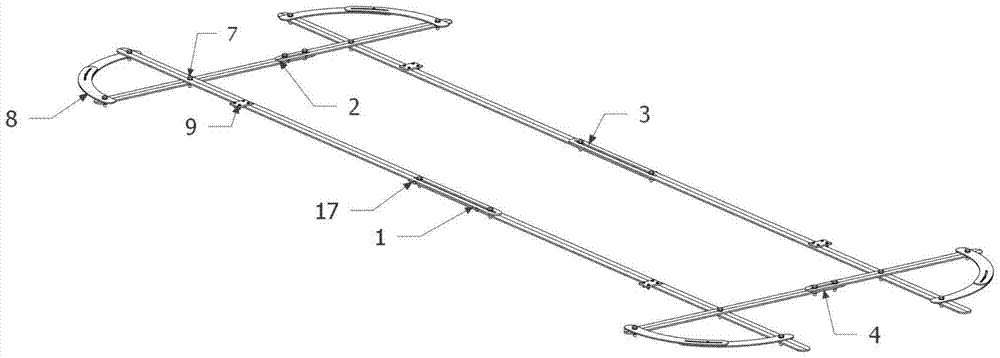
[0044] (1) Prepare the strut quick positioning device: see image 3 , the device is a steel structure, mainly composed of two sets of straight horizontal bars 1, two sets of straight vertical bars 2, and four sets of arc-shaped holding parts 8 connected by bolts; two sets of horizontal bars 1 and two sets of vertical bars 2 is fixed in the shape of a well, and the two ends of each of the four sets of holding parts 8 are respectively fixed on the ends of the adjacent horizontal bar 1 and the end of the vertical bar 2; two sets of horizontal bars 1 and two sets of vertical bars 2 can be straight The length of the telescopic adjustment rod, the ar...


PUM

PropertyMeasurementUnit
radiusaaaaaaaaaa
lengthaaaaaaaaaa

Abstract

The invention provides an installing construction method for a large blast furnace top valve box. Valve box supporting column installation is assisted through a rapid supporting column positioning device. Two sets of cross rods and two sets of vertical rods of the rapid supporting column positioning device can linearly stretch and contract for rod length adjustment, and four sets of clamping pieces of the rapid supporting column positioning device can stretch and contract through curves for clamping piece arc length adjustment. Supporting column top blind flange installing is assisted through a valve box supporting column top blind flange alignment device, and the valve box supporting column top blind flange alignment device is mainly formed by connecting an upper annular detachable steel structure and a lower annular detachable steel structure, and in other words, the valve box supporting column top blind flange alignment device is formed by connecting an upper adjusting end and a lower fixing end through a horizontal adjusting high-strength screw. According to the installing construction method, the installing and positioning accuracy of valve box supporting columns and blind flanges is improved, the installing precision of a furnace top valve box is improved, the error of the equipment manufacturing and installing process is effectively overcome, and the installing construction method has the advantages that time and labor are saved, the installing construction method is more convenient and more rapid, accuracy is high, safety is good, and cost is saved.

Description

technical field [0001] The invention relates to a method for installing and constructing metallurgical blast furnace bellless equipment, in particular to a method for installing and constructing a large-scale blast furnace top valve box. Background technique [0002] At present, the bellless top equipment of metallurgical blast furnaces is mainly composed of water-cooled gear boxes, glasses valves, receiving hoppers, upper and lower sealing valves, lower valve boxes, material tanks, swing flaps and other equipment. During the transportation of blast furnace raw materials, the lower valve box and material tank play the functions of weighing raw materials, storing and equalizing gas on this conveying line. Due to the heavy weight of the valve box, it also bears the weight of the upper material tank and the raw materials stored during work, while the equipment foundation of the lower valve box and the material tank (two parallel tanks or three parallel tanks) of large blast fur...

Claims


Application Information

Patent Timeline
Patent Type & Authority Patents(China)
IPC IPC(8): C21B5/00C21B7/18
CPCC21B5/00C21B7/18
Inventor 陈克明汪艳勇
Owner CHINA FIRST METALLURGICAL GROUP
Learn More