
Impeller assemblies, fans and air conditioners

A component and impeller technology, applied in the field of air-conditioning equipment, can solve the problem that the suction surface cannot be changed, etc.

Active Publication Date: 2018-01-05
GREE ELECTRIC APPLIANCES INC
View PDF6 Cites 0 Cited by
  • Summary
  • Abstract
  • Description
  • Claims
  • Application Information

AI Technical Summary

Problems solved by technology

[0005] The main purpose of the present invention is to provide a kind of impeller assembly, blower fan and air conditioner, to solve the problem that the suction surface in the prior art cannot be changed

Method used


Image

  • Impeller assemblies, fans and air conditioners
  • Impeller assemblies, fans and air conditioners
  • Impeller assemblies, fans and air conditioners

Examples


Embodiment Construction

[0025] It should be noted that, in the case of no conflict, the embodiments in the present application and the features in the embodiments can be combined with each other. The present invention will be described in detail below with reference to the accompanying drawings and examples.

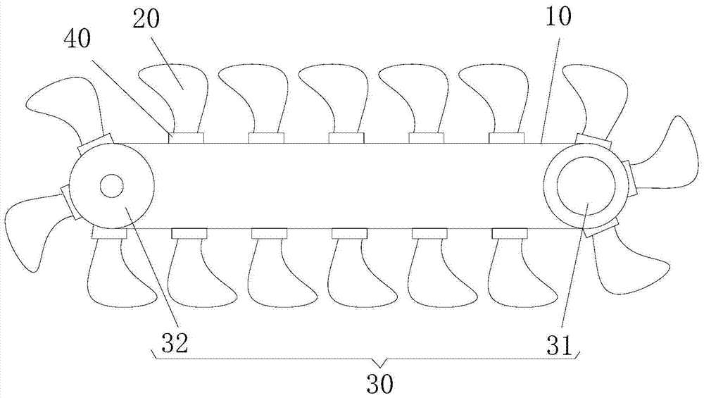
[0026] Such as image 3 As shown, the impeller assembly of this embodiment includes a flexible transmission member 10 and a plurality of fan blades 20 , the flexible transmission member 10 is connected end to end to form a ring, and the flexible transmission member 10 is rotatably arranged along the ring. A plurality of blades 20 are all connected to the flexible transmission member 10 , and the plurality of blades are arranged along the extending direction of the flexible transmission member 10 .

[0027] A plurality of fan blades 20 are driven by the flexible transmission member 10 to rotate around the ring formed by the flexible transmission member, and the suction surface of the fan can be...


PUM


Abstract

The invention provides an impeller assembly, a fan and air conditioning equipment. The impeller assembly comprises flexible transmission parts and a plurality of blades, wherein the flexible transmission parts are connected end to end to form a loop and rotationally arranged along the loop; the plurality of blades are connected onto the flexible transmission parts and arranged in the extension direction of the flexible transmission parts. With the adoption of the technical scheme, the plurality of blades are driven by the flexible transmission parts to rotate around the loop formed by the flexile transmission parts, the air suction surface of the fan can be changed according to the shape of the loop defined by the flexible transmission parts, and the problem that air suction surfaces of fans cannot be changed in the prior art is solved.

Description

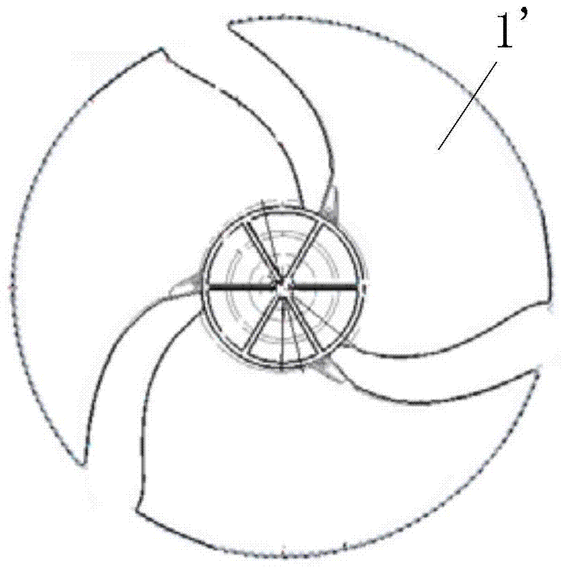
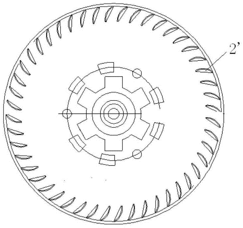
technical field [0001] The invention relates to the field of air-conditioning equipment, in particular to an impeller assembly, a fan and air-conditioning equipment. Background technique [0002] figure 1 A schematic structural view of an axial-flow impeller assembly in the prior art is shown, such as figure 1 As shown, the axial-flow fan blades in the prior art all adopt the method of arranging a plurality of axial-flow blades 1' in the circumferential direction of a rotating shaft. Although such axial-flow blades 1' can be designed to be thinner, they are limited by the rotating area. The air suction area is limited, and in order to obtain a large air volume or a large air inlet and outlet area, several fans need to be connected in parallel. The wind field is very uneven. [0003] The air suction surface of the axial flow fan in the prior art is a circular surface centered on the rotating shaft, and the air suction surface cannot be changed and is limited. [0004] f...

Claims


Application Information

Patent Timeline
Patent Type & Authority Patents(China)
IPC IPC(8): F04D29/32
CPCF04D29/325
Inventor 魏亮
Owner GREE ELECTRIC APPLIANCES INC
Learn More