Finned tube heat exchanger and air conditioner

A technology of heat exchanger and tube-fin type, which is applied in the field of tube-fin heat exchanger and air conditioner, can solve the problem that the air conditioner cannot obtain better heating effect, so as to reduce the impact, ensure the smoothness, and ensure the The effect of thermal effects

Inactive Publication Date: 2016-04-13
GD MIDEA AIR-CONDITIONING EQUIP CO LTD +1
View PDF10 Cites 17 Cited by
  • Summary
  • Abstract
  • Description
  • Claims
  • Application Information

AI Technical Summary

Problems solved by technology

[0003] The purpose of the present invention is to overcome at least one disadvantage of the above-mentioned prior art, and provide a tube-fin heat exchanger and an air conditioner, which solves the problem that the air conditioner cannot obtain better heating effect in both ultra-low temperature environment and low temperature environment technical problem

Method used


Image

  • Finned tube heat exchanger and air conditioner
  • Finned tube heat exchanger and air conditioner
  • Finned tube heat exchanger and air conditioner

Examples


specific Embodiment approach 1

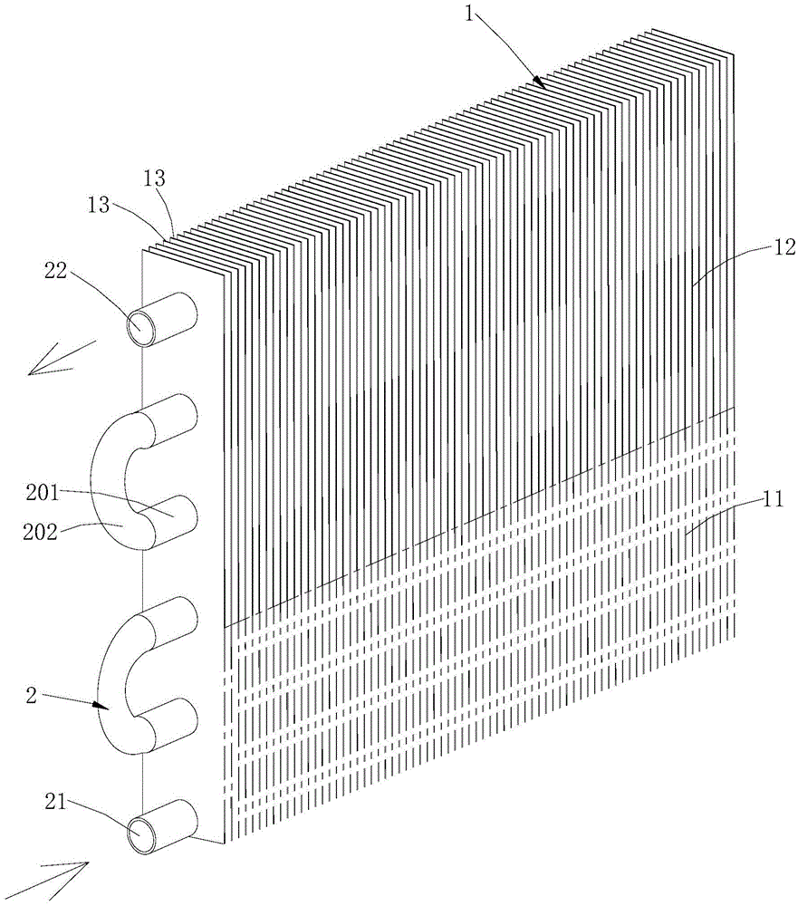
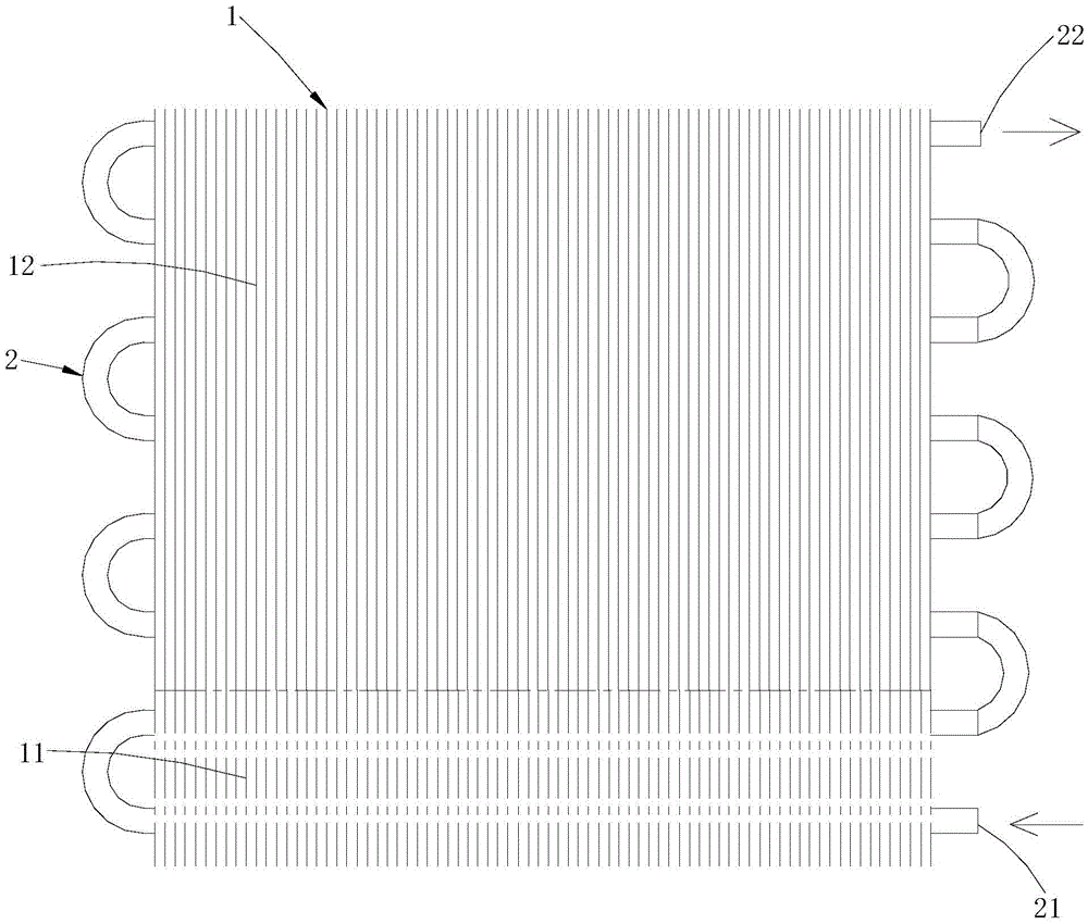
[0034] together with reference figure 1 and figure 2 As shown, in this specific embodiment, the tube-fin heat exchanger is a single-flow heat exchanger, that is, a heat exchanger with only one refrigerant heat exchange process (one-in-one-out heat exchanger), and the first port 21 number, the number of second ports 22 , the number of hydrophilic regions 11 and the number of hydrophobic regions 12 are all one, and the hydrophilic region 11 is located below the hydrophobic region 12 . When the tube-fin heat exchanger is used as an evaporator, the first port 21 is the refrigerant inlet, and the second port 22 is the refrigerant outlet. During the specific heat exchange process, the refrigerant with a lower temperature enters the fin assembly 1 from the first port 21 heat exchange in the hydrophilic area 11 of the fin assembly 1, and then enter the hydrophobic area 12 of the fin assembly 1 for further heat exchange, and finally leave the tube-fin heat exchanger from the second p...

specific Embodiment approach 2

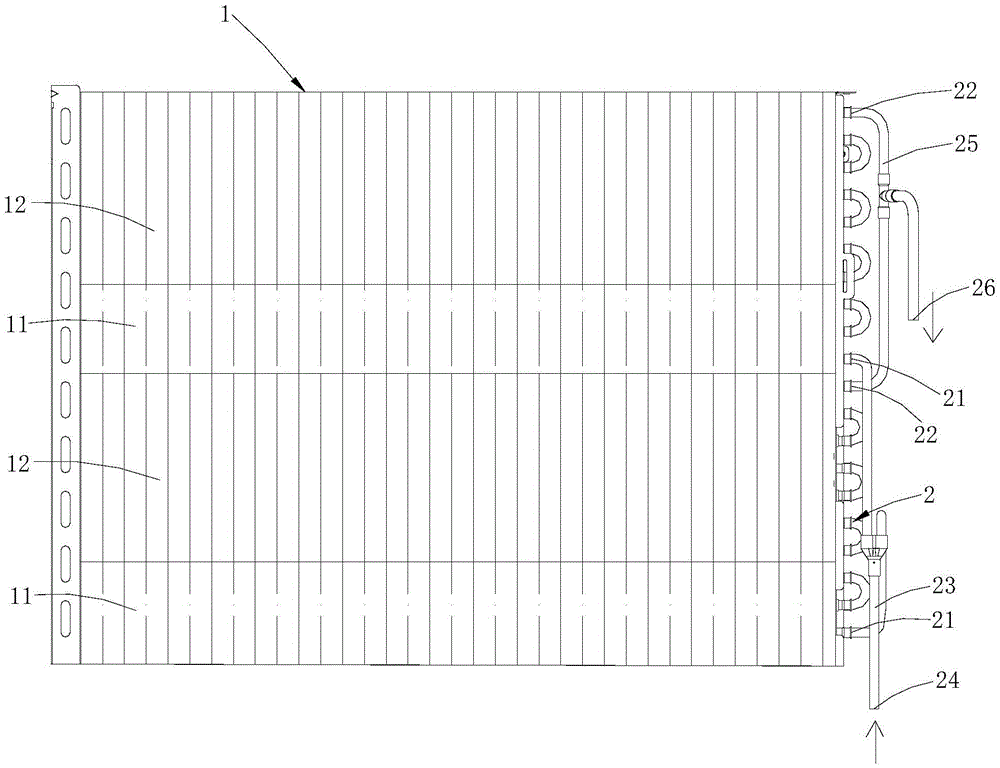
[0036] refer to image 3 As shown, in this specific embodiment, the tube-fin heat exchanger is a multi-process heat exchanger, which has at least two heat exchangers (multi-input and multi-outlet heat exchangers) in parallel refrigerant heat exchange processes, and the first port 21, the number of second ports 22, the number of hydrophilic regions 11 and the number of hydrophobic regions 12 are all the same and at least two, each hydrophobic region 12 and each hydrophilic region 11 are on the fin assembly 1 along it The distribution arrangement direction is alternately distributed from top to bottom. When the tube-fin heat exchanger is used as an evaporator, each first port 21 is a refrigerant inlet, and each second port 22 is a refrigerant outlet. 21 enters the hydrophilic regions 11 of the fin assembly 1 for heat exchange, then enters the hydrophobic regions 12 of the fin assembly 1 for further heat exchange, and finally leaves the tube-fin heat exchanger through the second...

specific Embodiment approach 3

[0041] refer to Figure 4 As shown, in this specific embodiment, the tube-fin heat exchanger is also a multi-pass heat exchanger, but it is different from the above specific embodiment two in that: refer to image 3 As shown, in the second specific embodiment, after the refrigerant enters the tube-fin heat exchanger, it is branched into multiple branches, and then the multiple branches enter different regions of the fin assembly 1 for heat exchange; while referring to Figure 4As shown, in this specific embodiment, after the refrigerant enters the tube-fin heat exchanger, it will first enter a region of the fin assembly 1 for heat exchange, and then branch into multiple branches, and then make the multiple branches respectively enter into other different regions of the fin assembly 1 for heat exchange. Specifically, the number of second ports 22, the number of hydrophilic regions 11 and the number of hydrophobic regions 12 are the same and at least two, the number of first po...


PUM


Abstract

The invention discloses a finned tube heat exchanger and an air conditioner which are suitable for the field of air conditioners. The finned tube heat exchanger comprises a fin assembly and a heat exchange tube assembly installed on the fin assembly in a penetrating manner. The fin assembly is provided with at least one hydrophilic region and at least one hydrophobic region. The heat exchange assembly is provided with at least one first port through which a refrigerating medium enters the hydrophilic regions for heat exchange when the finned tube heat exchanger serves as an evaporator and at least one second port through which the refrigerating medium is drained out of the hydrophobic regions for finishing heat exchange when the finned tube heat exchanger serves as the evaporator. When the finned tube heat exchanger serves as the evaporator, the refrigerating medium enters the hydrophilic regions from the first ports for heat exchange, after heat exchange is finished, the refrigerating medium is drained from the hydrophobic regions through the second ports, and therefore the good heat exchange effect of the finned tube heat exchanger in different temperature environments and different working conditions can be achieved.

Description

technical field [0001] The invention belongs to the field of air conditioners, in particular to a tube-fin heat exchanger and an air conditioner. Background technique [0002] As a commonly used heat exchanger, the tube-fin heat exchanger has been widely used in the air-conditioning industry. In the prior art, in order to improve the heating effect of the air conditioner in an ultra-low temperature environment (the outdoor temperature is minus 7°C to minus 30°C), measures of hydrophilic treatment on the surface of the fins are generally taken. Although the existing air conditioner can achieve better heating effect in the ultra-low temperature environment, the heating effect in the low temperature environment (outdoor temperature is 4°C to minus 7°C) is not ideal, the reason is: this When this kind of air conditioner is heating in a low temperature environment, it will form a continuous flow of condensed water on the entire fin surface, which will hinder the smooth flow of a...

Claims


Application Information

Patent Timeline
Patent Type & Authority Applications(China)
IPC IPC(8): F25B39/02F25B39/04
CPCF25B39/02F25B39/04F28D1/0477
Inventor 李丰
Owner GD MIDEA AIR-CONDITIONING EQUIP CO LTD
Why Eureka
Try Eureka