
Method and device for positioning magnetic foreign body, and magnetic resonance device

A positioning method and technology for a positioning device are applied in the direction of magnetic resonance measurement, etc., which can solve the problems of the basic magnetic field uniformity destruction of the magnetic resonance device, affecting the imaging quality of the magnetic resonance device, and spending a lot of time, so as to reduce the workload and improve the utilization rate. Efficiency, the effect of avoiding search work

Active Publication Date: 2016-04-13
SIEMENS SHENZHEN MAGNETIC RESONANCE
View PDF9 Cites 0 Cited by
  • Summary
  • Abstract
  • Description
  • Claims
  • Application Information

AI Technical Summary

Problems solved by technology

These magnetic foreign objects will destroy the uniformity of the basic magnetic field of the magnetic resonance device, thereby affecting the imaging quality of the magnetic resonance device
[0003] For these magnetic foreign bodies that are accidentally brought into the magnetic resonance device, at present, only manpower can be used to search, especially when the color of the magnetic foreign matter is close to the background color of the magnetic resonance device, it takes a lot of time and physical effort to find these small foreign body

Method used


Image

  • Method and device for positioning magnetic foreign body, and magnetic resonance device
  • Method and device for positioning magnetic foreign body, and magnetic resonance device
  • Method and device for positioning magnetic foreign body, and magnetic resonance device

Examples


Embodiment Construction

[0027] In order to make the purpose, technical solution and advantages of the present invention clearer, the following examples are given to further describe the present invention in detail.

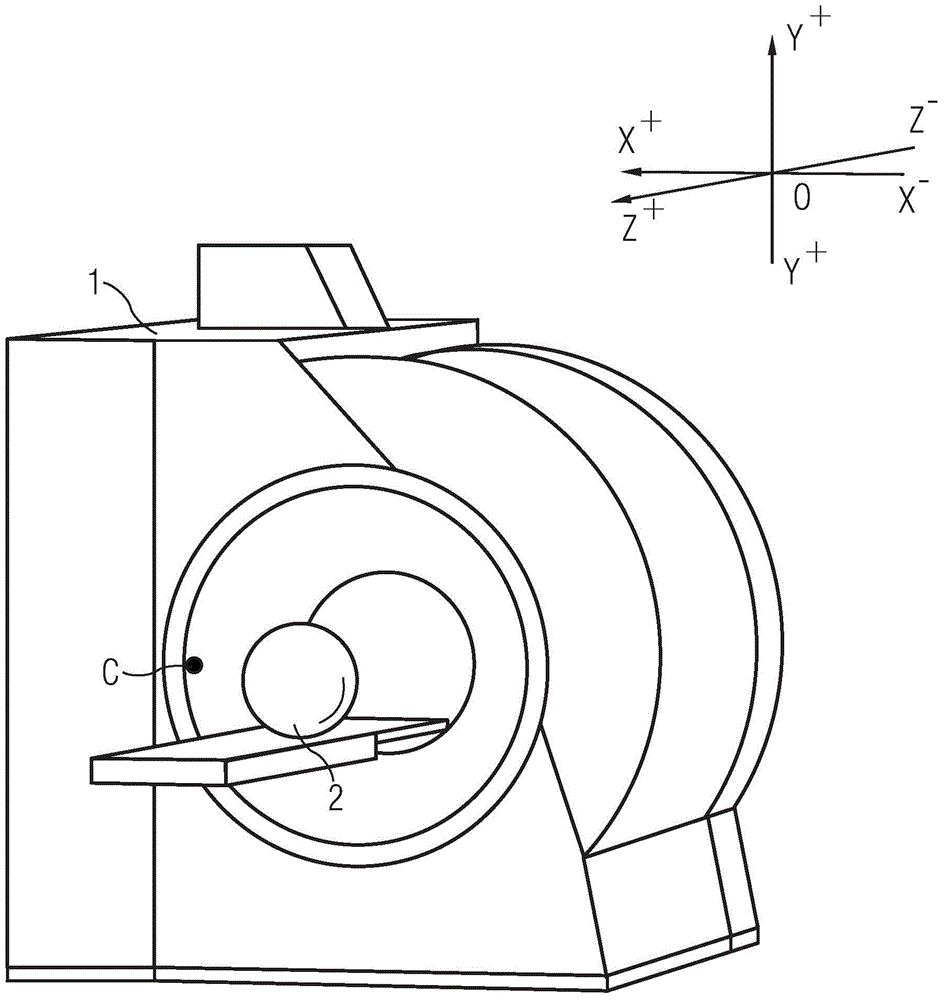
[0028] figure 1 A flow chart of the magnetic foreign body positioning method involved in the present invention is shown. In this embodiment, a magnetic resonance imaging apparatus is taken as an example for description.

[0029] In applying the method for locating magnetic foreign objects of the present invention, it is first necessary to measure the initial magnetic field without magnetic foreign objects in the magnet in advance, and store the measured coefficients of the first spherical harmonic function representing the initial magnetic field in the database (step S101) . Specifically, in this embodiment, the initial magnetic field OriField under the condition that no magnetic foreign matter exists in the magnetic resonance imaging apparatus is measured. The measurement of the init...


PUM

PropertyMeasurementUnit
Cone angleaaaaaaaaaa

Abstract

The invention provides a method and a device for positioning magnetic foreign bodies, and a magnetic resonance device. The method and the device are used to determine positions of magnetic foreign bodies in a magnet. The method comprises: a step of obtaining initial magnetic field parameters, including measuring field intensity of an initial magnetic field when the magnetic foreign body does not exist, and calculating a first spherical harmonic function coefficient representing the initial magnetic field; a step of obtaining current magnetic field parameters, including measuring field intensity of the current magnetic field of the magnet, the field intensity being changed since a magnetic foreign body is put in the initial magnetic field, and calculating a second spherical harmonic function coefficient representing the current magnetic field; a step of obtaining variation magnetic field parameters, including comparing the first spherical harmonic function coefficient with the second spherical harmonic function coefficient, to obtain a third spherical harmonic function coefficient related to a variation magnetic field; a step of reestablishing the variation magnetic field, including according to the third spherical harmonic function coefficient, reestablishing the variation magnetic field; and a step of positioning the magnetic foreign body, according to the reestablished variation magnetic field, determining the position of the magnetic foreign body relative to the magnet.

Description

technical field [0001] The invention relates to a method, a device and a magnetic resonance device for locating magnetic foreign matter introduced into a magnet. Background technique [0002] Magnetic resonance devices have high requirements on the uniformity of the basic magnetic field. Generally speaking, the better the uniformity of the basic magnetic field, the higher the quality of the imaging image. However, sometimes when the patient is examined, the patient will occasionally bring in foreign objects such as coins and hairpins. When the magnetic resonance device starts to work, these magnetic foreign objects will adhere to a certain position of the device due to the magnetic force generated by the magnetic resonance device. place. These magnetic foreign objects will cause damage to the uniformity of the basic magnetic field of the magnetic resonance device, thereby affecting the imaging quality of the magnetic resonance device. [0003] For these magnetic foreign bo...

Claims


Application Information

Patent Timeline
IPC IPC(8): G01R33/32
Inventor 匡斌岳振华
Owner SIEMENS SHENZHEN MAGNETIC RESONANCE
Learn More