A bending-torsion coupling piezoelectric drive crawler driving device and its working method

A piezoelectric drive and driving device technology, applied in the direction of piezoelectric effect/electrostrictive or magnetostrictive motors, generators/motors, electrical components, etc., can solve the problem of piezoelectric ceramics being fragile and electromechanical coupling efficiency Low, slow movement speed and other issues, to achieve the effect of flexible structure, high electromechanical coupling efficiency, and fast speed

Inactive Publication Date: 2017-10-10
NANJING UNIV OF AERONAUTICS & ASTRONAUTICS
View PDF1 Cites 0 Cited by
  • Summary
  • Abstract
  • Description
  • Claims
  • Application Information

AI Technical Summary

Problems solved by technology

Although this system abandons the sprockets, idlers and road wheels necessary for traditional tracked vehicles, it has the advantages of simple structure, high mechanical integration, strong environmental adaptability and high driving efficiency, but due to the proposed piezoelectric transducer The metal elastic body is used to excite the piezoelectric ceramic sheet. This excitation method uses the vibration mode of the piezoelectric ceramic, and the electromechanical coupling efficiency of energy conversion is low. At the same time, it is limited by the strength and fatigue life of the adhesive layer. It has the disadvantages of slow movement speed, small driving force, poor stability and fragile piezoelectric ceramics

Method used


Image

  • A bending-torsion coupling piezoelectric drive crawler driving device and its working method
  • A bending-torsion coupling piezoelectric drive crawler driving device and its working method
  • A bending-torsion coupling piezoelectric drive crawler driving device and its working method

Examples


Embodiment Construction

[0023] The present invention will be further described below in conjunction with the accompanying drawings and specific embodiments.

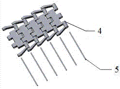
[0024] The bending-torsion coupling type piezoelectric driving crawler traveling device provided by the present invention includes a metal crawler 1 , two ring members 2 and a variable-section piezoelectric transducer 3 . The variable-section piezoelectric transducer 3 includes a variable-section beam 3-1, two pre-tightening wedge devices 3-2, a first torsional vibration piezoelectric ceramic sheet 3-3, an input electrode sheet 3-4, a second torsional vibration Piezoelectric ceramic sheet 3-5, ground electrode sheet 3-6, first bending vibration piezoelectric ceramic sheet 3-7, second bending vibration piezoelectric ceramic sheet 3-8, third torsional vibration piezoelectric ceramic sheet 3-9 , the fourth torsional vibration piezoelectric ceramic sheet 3-10, the third bending vibration piezoelectric ceramic sheet 3-11, and the fourth bending vibr...


PUM


Abstract

The invention provides a bend-twist coupling type piezoelectric driving track traveling device and a working method thereof. The device comprises a metal track, two annular components and a variable cross-section piezoelectric transducer, wherein the annular components are arranged at two ends of the variable cross-section piezoelectric transducer; the variable cross-section piezoelectric transducer comprises a plurality of sets of piezoelectric ceramic pieces, two pre-tightening wedge blocks and a variable cross-section beam; and the piezoelectric ceramic pieces are arranged in a certain order and are fixed in a groove of the variable cross-section beam through the pre-tightening wedge blocks. According to the bend-twist coupling type piezoelectric driving track traveling device and the working method thereof, by stimulating the piezoelectric ceramic pieces, a torsional vibration mode and a bending vibration mode are stimulated on the variable cross-section beam, so that a traveling wave, with n (n being greater than or equal to 2) wave crests and wave troughs shown all together, rotating along the peripheral direction is coupled on the annular components, the mass points on the outer surfaces of the annular components carry out micro-amplitude elliptical motions and drive the metal track to move through the action of friction, and the device has the advantages of compact structure, large force (torque) weight ratio, high environmental suitability, structure form flexibility, high speed, high electro-mechanical coupling efficiency and the like.

Description

technical field [0001] The invention relates to the technical field of piezoelectric actuation, in particular to a bending-torsion coupling piezoelectric-driven crawler traveling device and a working method thereof. Background technique [0002] As an important part of the development of space science, interstellar exploration has always been highly valued and invested heavily by countries all over the world. As the carrier and actuator of planetary exploration missions, the development of planetary surface inspection probes is of great significance for the exploration and further development of unknown planets. The crawler driving system has a strong ability to overcome obstacles in an environment with low gravitational acceleration and a strong ability to adapt to the rough and complex shape of the lunar surface, which is very beneficial to planetary exploration missions. , high energy consumption, easy to be worn by the surface soil of the planet, and the need for lubric...

Claims


Application Information

Patent Timeline
Patent Type & Authority Patents(China)
IPC IPC(8): H02N2/16
CPCH02N2/16
Inventor 王亮舒承有蒋正金家楣
Owner NANJING UNIV OF AERONAUTICS & ASTRONAUTICS
Why Eureka
Try Eureka