
Multi-AP cooperation based interference elimination method in dense WLAN environment

An interference elimination and environmental technology, applied in the field of communication, can solve the problems of reduced AP throughput, reduced number of users, and not very dense network coverage, etc., and achieve the effect of improving system capacity and eliminating interference

Inactive Publication Date: 2016-04-13
XIDIAN UNIV
View PDF3 Cites 5 Cited by
  • Summary
  • Abstract
  • Description
  • Claims
  • Application Information

AI Technical Summary

Problems solved by technology

[0009] When the network coverage is not very dense and the interference is not very serious, the above solution can be optimized; however, in a densely deployed WLAN environment, the mutual interference between access points makes the above anti-interference solution very limited
Aiming at the mutual interference between APs in the above-mentioned dense WLAN environment, related solutions have emerged in recent years. On the one hand, it is to reduce the transmit power of APs or dynamically shut down There is no mutual interference or very little interference between APs. Although this method can reduce the signal interference between APs, it reduces the number of users served by a single AP; on the other hand, when an AP When communicating with the station STA, the interfered access point AP suspends communication until the end of the communication. Although this method can effectively avoid network conflicts, it causes the throughput of the interfered access point AP to be greatly reduced.

Method used


Image

  • Multi-AP cooperation based interference elimination method in dense WLAN environment
  • Multi-AP cooperation based interference elimination method in dense WLAN environment
  • Multi-AP cooperation based interference elimination method in dense WLAN environment

Examples


Embodiment Construction

[0027] Below with reference to accompanying drawing, the present invention is described in detail:

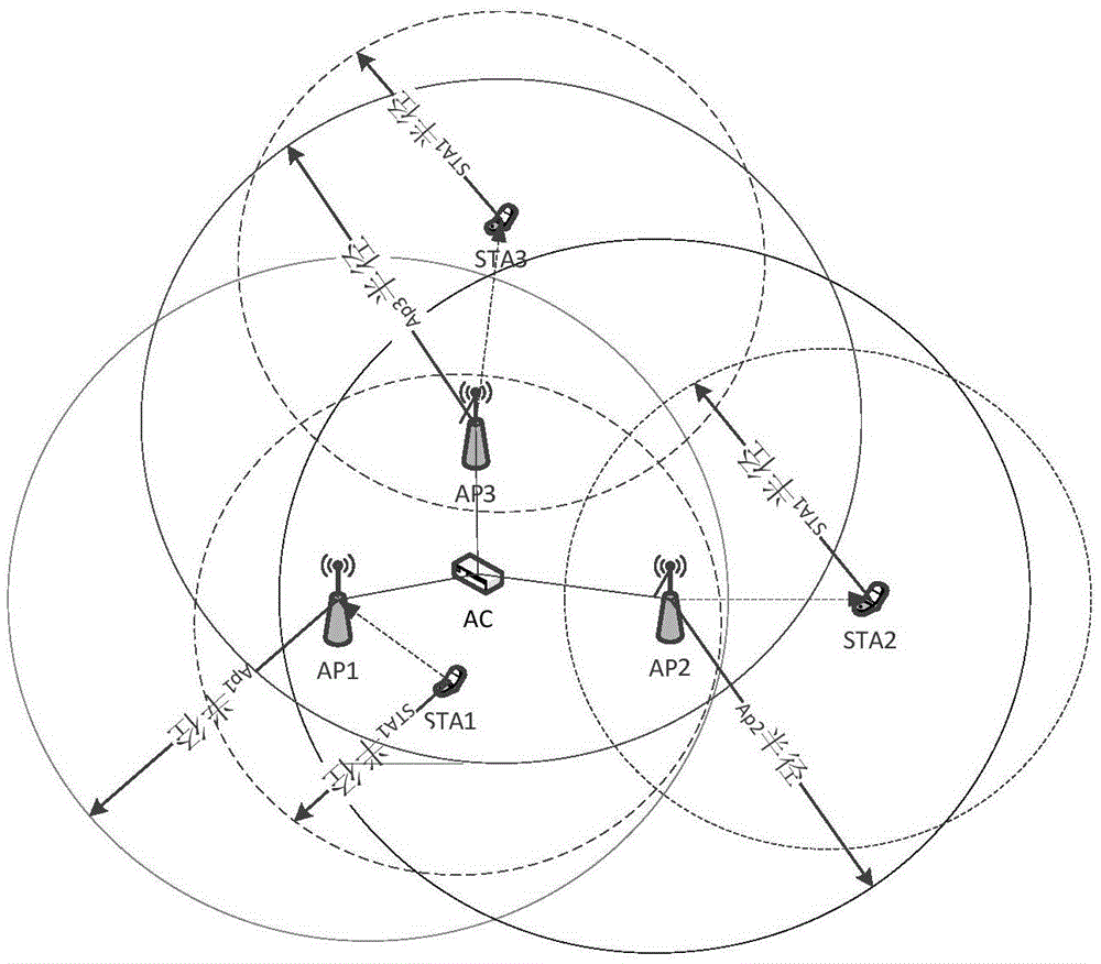
[0028] refer to figure 1 , the scene used in the present invention is a scene of mutual interference between multiple APs in a dense WLAN environment, which includes three access points AP1, AP2, AP3 and three stations STA1, STA2, STA3 and an access controller AC . The station associated with the first access point AP1 is the first station STA1, the station associated with the second access point AP2 is the second station STA2, and the station associated with the third access point AP3 is the third station STA3. These three access points AP1, AP2 and AP3 interfere with each other. The second access point AP2 and the third access point AP3 can receive the RTS frame sent by the first station STA1 to the first access point AP1, and the second access point AP2 and the third access point AP3 can also receive the RTS frame sent by the first station STA1 to the first access point AP...


PUM


Abstract

The invention discloses a multi-AP cooperation based interference elimination method in a dense WLAN environment, mainly for solving the problems of mutual interference between access points and low system capacity in the prior art. The method comprises the following realization steps: in a communication process between a site and a current access point, other neighbor access points determining whether to send data, and if so, the neighbor access point directly sending the data and waiting for the site to replay a confirmation character; after the neighbor access point sends the data, transmitting the data to the current access point through a wired mode; the current access point, by use of a physical layer network encoding technology, performing demodulation mapping on received pollution signals and then determining an initial position of pollution by use of lead code correlation; and directly performing bit XOR after the initial position, and recovering original data from the pollution signals so as to eliminate interference signals. According to the invention, downlink service transmission of the neighbor access points and sites associated therewith is realized while the interference is eliminated, the system capacity is improved, and the method provided by the invention can be applied to a densely disposed WLAN environment.

Description

technical field [0001] The invention belongs to the technical field of communication, and in particular relates to an interference elimination method, which can be used to realize interference elimination through wired connection cooperation among access points APs in a densely deployed WLAN environment, and improve system capacity. Background technique [0002] With the rapid development of the wireless local area network (WLAN), the interference in the WLAN greatly reduces the channel utilization. Interference in WLAN mainly includes two types of interference within the system and interference outside the system. For interference outside the system, for example, co-location or combination of WLAN with the existing GMS network, TD network and future LTE network, especially in the 2.3GHZ frequency band The interference of LTE to WLAN is particularly serious; other devices including microwave ovens, cordless phones, Bluetooth, etc. will also cause interference; for interferen...

Claims


Application Information

Patent Timeline
IPC IPC(8): H04W72/08
CPCH04W72/541
Inventor 侯蓉晖刘意李建东李红艳
Owner XIDIAN UNIV
Learn More