Joining structure

A technology of structure and joint, applied in the direction of superstructure, subassembly of superstructure, transportation and packaging, etc., can solve problems such as poor mechanical properties, achieve the effects of improving rigidity, suppressing stress generation, and reducing deformation

Inactive Publication Date: 2016-04-13
SUZUKI MOTOR CORP
View PDF5 Cites 4 Cited by
  • Summary
  • Abstract
  • Description
  • Claims
  • Application Information

AI Technical Summary

Problems solved by technology

Resin materials have a smaller specific gravity than metal materials such as iron and aluminum, but have poorer mechanical properties

Method used


Image

  • Joining structure
  • Joining structure
  • Joining structure

Examples


no. 1 Embodiment approach

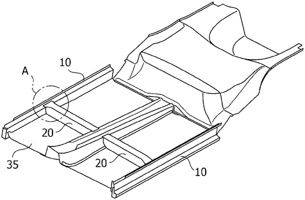
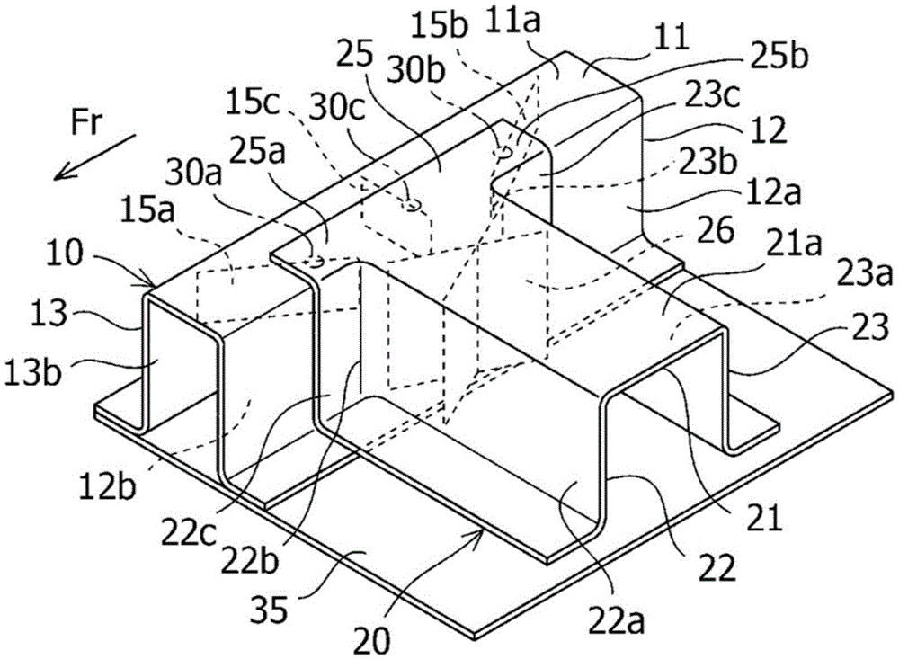
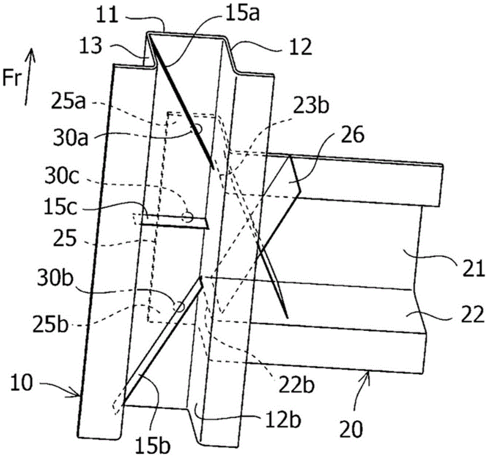
[0037] use Figure 1 ~ Figure 4 The first embodiment will be described. Such as figure 1As shown, the side member 10 of this embodiment is a member constituting the skeleton of the vehicle body, extends in the vehicle front-rear direction, and is arranged in pairs on both sides in the vehicle width direction. The side member 10 of this example is formed of a fiber-reinforced resin material. The cross member 20 is a member constituting the frame of the vehicle body similarly to the side member 10 . The cross member 20 is a member extending in the vehicle width direction, and is joined to a side portion of the side member 10 .

[0038] As mentioned above, resin materials have a smaller specific gravity than metal materials such as iron and aluminum, but have inferior mechanical properties. Fiber-reinforced resin materials are materials that use carbon fibers and glass fibers to supplement poor mechanical properties. In this example, for example, a glass fiber material such...

no. 2 Embodiment approach

[0067] use Figure 5 The second embodiment will be described. This embodiment is the first embodiment ( Figure 1 ~ Figure 4 ) in the modified example, the same reference numerals are assigned to the same or similar parts as those in the first embodiment, and repeated descriptions are omitted.

[0068] In this embodiment, if Figure 5 As shown, the inner side of the beam 20 is provided with a U-shaped rib 29 in Katakana. The Katakana U-shaped rib 29 is composed of a rectangular plate attached to the back of the three surfaces of the second upper surface 21a, the front vertical wall surface 22a, and the rear vertical wall surface 23a, respectively.

[0069] The Japanese Katakana U-shaped rib 29 may also be arranged in the vicinity of the joining portion similarly to the letter X-shaped rib 26 .

[0070] According to the present embodiment, by providing the Japanese Katakana U-shaped rib 29 and the like on the crossbeam 20 similarly to the arrangement of the letter X-shaped ...


PUM


Abstract

The present invention enables the rigidity of a bending load that acts on a T-shaped joining section to be improved. The joining structure has a second member 20 joined to a side section of the first member 10, forms a T shape, and has a first upper surface 11a and a flange 25 that are joined at a joining section 30. A long rib 15a is provided on the rear surface of the first upper surface 11a. The total length of the long rib 15a is set to at least twice the length to a joining section 30a from a contact section between the first member 10 and the second member 20. Of the angles formed between the extension directions of the long rib 15a and the longitudinal direction of the second member 20, the angle formed on the opposite side to the second member 20 is acute.

Description

technical field [0001] The present invention relates to a joining structure in which two members formed of a fiber-reinforced resin material are joined in a T-shape. Background technique [0002] Among the configurations joined in a T-shape, for example, there are configurations where members for forming a frame of an automobile are joined. For example, the joint between the longitudinal beam and the cross beam has a T-shaped joint structure. [0003] The side member is a member extending in the vehicle front-rear direction, and the cross member is a member extending in the vehicle width direction. The technique disclosed in Patent Document 1, for example, is known for coupling these components. [0004] Patent Document 1 discloses that rigidity and strength are improved by providing a beam on a member in a direction against deformation. This technology is to reinforce the side sill in case the side sill combined with the center pillar is subjected to torsional input due ...

Claims


Application Information

Patent Timeline
Patent Type & Authority Applications(China)
IPC IPC(8): B62D29/04B62D25/20
CPCB62D29/048B62D25/2036B62D29/041
Inventor 村瀬祐大
Owner SUZUKI MOTOR CORP
Why Eureka
Try Eureka