Transmission system
A transmission system and transmission machine technology, applied in the field of radio wave transmission system, can solve problems such as thermal shock of substrate parts, temperature drop, equipment condensation, etc.
- Summary
- Abstract
- Description
- Claims
- Application Information
AI Technical Summary
Problems solved by technology
Method used
Image

Examples
no. 1 Embodiment approach
[0024] [structure]
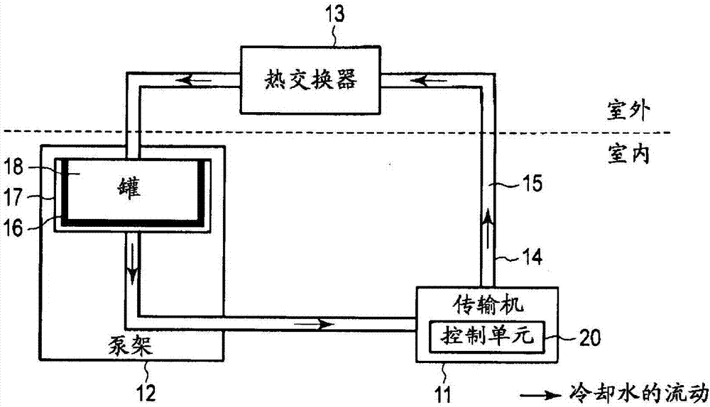
[0025] figure 1 It is a block diagram showing an example of the transmission system according to the first embodiment. This transport system includes a conveyor 11 , a pump rack 12 and a heat exchanger 13 . The conveyor 11 and the pump rack 12 are installed indoors, and the heat exchanger 13 is installed outdoors.
[0026] The conveyor 11 , the pump frame 12 and the heat exchanger 13 are connected by a pipe 14 filled with cooling water 15 . For the cooling water 15 , for example, antifreeze is used in order to prevent clogging of flow paths and damage to pipes due to freezing.
[0027] The conveyor 11 includes a control unit 20 . The control unit 20 circulates the cooling water through the drive of the heat exchanger 13 and the pump frame 12 during the operation of the conveyor 11 . The control unit 20 stops the circulation of the cooling water generated by the drive of the heat exchanger 13 and the pump frame 12 when the conveyor 11 is stopped.
[0...
no. 2 Embodiment approach
[0040] [structure]
[0041] Figure 4 as well as Figure 5 An example of the transmission system according to the second embodiment is shown. In these figures, with figure 1 The difference is that the heat storage member 16 is accommodated inside the tank 18 . The heat storage member 16 is, for example, Figure 4 A spherical shape as shown can be contained in a container. Alternatively, the thermal storage member 16 is Figure 5 It can be wrapped in a container in the form of a sheet as shown.
[0042] [effect]
[0043] The conveyor 11, the pump stand 12, the heat exchanger 13, the piping 14, and the cooling water 15 function in the same manner as in the first embodiment. The heat storage member 16 is in direct contact with the cooling water stored in the tank 18 , and recovers the heat of the conveyor 11 that has taken the cooling water 15 . Similar to the first embodiment, the heat storage member 16 changes from a solid to a liquid at a preset melting point, and sto...
no. 3 Embodiment approach
[0046] [structure]
[0047] Image 6 It is a block diagram showing an example of the transmission system according to the third embodiment. and figure 1 The difference is that the tank 18 is removed and the heat storage member 16 is installed on the surface of the outdoor piping 14 . The heat storage member 16 includes a pair of electrodes 21 . The control unit 20 is able to apply a voltage to the heat storage member 16 via the electrodes 21 .
[0048] [effect]
[0049] The conveyor 11, the pump stand 12, the heat exchanger 13, the piping 14, and the cooling water 15 function in the same manner as in the first embodiment. The heat storage member 16 attached to the piping 14 outdoors recovers the heat of the conveyor 11 that has received the cooling water 15 via the piping 14 . The heat storage member 16 changes from a solid to a liquid at a predetermined melting point, and stores heat generated by the conveyor 11 as latent heat.
[0050] The control unit 20 applies a vo...
PUM
 Abstract
Description
Claims
Application Information
 - Generate Ideas
- Intellectual Property
- Life Sciences
- Materials
- Tech Scout
- Unparalleled Data Quality
- Higher Quality Content
- 60% Fewer Hallucinations
Browse by: Latest US Patents, China's latest patents, Technical Efficacy Thesaurus, Application Domain, Technology Topic, Popular Technical Reports.
© 2025 PatSnap. All rights reserved.Legal|Privacy policy|Modern Slavery Act Transparency Statement|Sitemap|About US| Contact US: help@patsnap.com