
Hand-pressing cloth clamping mop

A clamping and mop technology, which is applied in the field of hand-pressed mop replacement mop cloth, can solve the problems of complex structure, multiple springs, and difficult control of force, and achieve the effect of simplifying the structure of the mop, reducing the height of the shell body, and reducing the number of uses

Inactive Publication Date: 2016-04-20
CHENGDU UNIVERSITY OF TECHNOLOGY +1
View PDF11 Cites 0 Cited by
  • Summary
  • Abstract
  • Description
  • Claims
  • Application Information

AI Technical Summary

Problems solved by technology

However, they all use the method of foot towers to clamp the mop. The disadvantages of this method are: due to the poor flexibility of the feet, it is inconvenient to operate, and the power is not easy to control, and it is easy to damage the device.
In addition, the force point of their stepping is offset from the center of the device, it is not easy to distribute the pressure evenly on the mop, and it is easy to miss or roll down
What's more, they all need more pairs of gears, racks and more springs, resulting in a complex structure, which is unfavorable for the working characteristics of the mop (the force is more random) and the environment (contact with water and humidity)

Method used


Image

  • Hand-pressing cloth clamping mop
  • Hand-pressing cloth clamping mop
  • Hand-pressing cloth clamping mop

Examples


Embodiment Construction

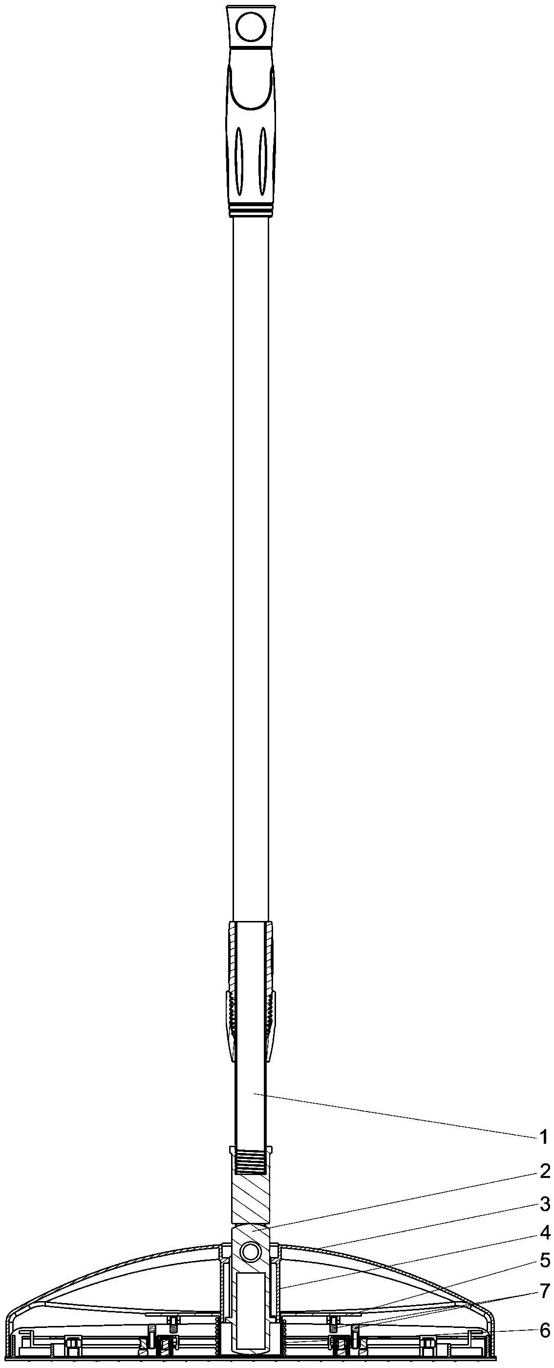
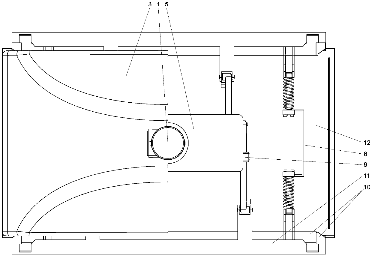
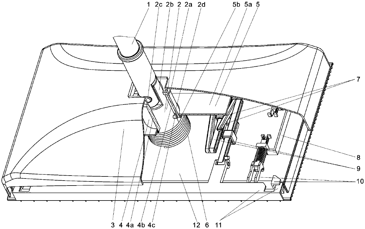
[0035] Such as Figure 1 to Figure 6 As shown, a hand-pressed cloth mop includes a mop rod 1, a movable column 2, a casing 3, a sleeve 4, a transmission plate 5, a spring 6, a connecting rod 7, an inner claw slide bar 8, an outer claw slide bar 9, Inner claw 10, outer claw 11, base plate 12, up and down positioning device.

[0036] Described mop bar 1 is similar to existing mop bar, and its lower end has a U-shaped hinge with a hole.

[0037] The housing 3 is a cover with a lower opening. The bottom plate 12 is a rectangular plate body, the upper end is connected with the casing, and the lower end surface is used for laminating the mop cloth. The outer claws 11 are used for hooking the mop. The outer claw slide bar 9 is slidably connected with the base plate 12, and can slide forward and backward. One end is hinged with the outer claw 11, and the other end has a pin joint. The inner claws 10 cooperate with the outer claws 11 to form a pair of clamping parts, and under the ...


PUM


Abstract

The invention discloses a hand-pressing cloth clamping mop which comprises a movable column, a sleeve, an up-and-down positioning device, a driving plate, a spring and connecting rods. The movable column is matched with the sleeve and can slide up and down in the sleeve. The up-and-down positioning device is a device capable of positioning the movable column on the upper position and the lower position of the sleeve by operating a mop rod. A plate body is a rectangular plate part provided with a hole in the center, a concave cup is a cup-shaped part concaved downwards and located on the center position of the plate body, an upper opening is connected with the center hole in the plate body in a matched mode, and the movable column extends into the concave cup. Connecting lugs are arranged at the left end and the right end of the plate body, the upper end of the spring is arranged on the concave cup in a sleeving mode, the upper face of the spring acts on the driving plate, and the bottom face of the spring acts on a base plate. The upper end of each connecting rod is hinged to a driving plate connecting lug hinged point, and the lower end of each connecting rod is hinged to an outer claw sliding rod hinged point. When the driving plate is pressed downwards, the connecting rods push an outer claw sliding rod to make outer claws to move inwards to clamp a mop cloth. Operation is conducted manually, flexibility and convenience are achieved, and operation force is easy to control and master; multiple outer claw pull rod springs and multiple pairs of gears and racks are omitted structurally, and the hand-pressing cloth clamping mop is simple in structure and durable.

Description

technical field [0001] The invention relates to a household cleaning tool, in particular to a hand-pressed mop for changing mop cloth. Background technique [0002] Mop is a cleaning tool commonly used in family life, and especially clamp cloth type mop has entered family more and more. The cloth mop is usually directly replaced and clamped by hand. For example, the Chinese patent "A Cloth Mop" with the publication number CN201806663U belongs to this type. The disadvantage of this type is that the mop must be rolled up by hand. Then the clamp is clamped by hand, which is extremely inconvenient and unhygienic to operate, and the operation needs to be boarded, which is very laborious. In order to solve these problems, some solutions have occurred, such as the Chinese patent "cloth-type mop" whose publication number is CN2703488Y, the Chinese patent "foot stepping on a cloth mop" whose publication number is 202341960U, and the Chinese patent "a cloth mop" whose publication num...

Claims


Application Information

Patent Timeline
IPC IPC(8): A47L13/256A47L13/20A47L13/24
CPCA47L13/256A47L13/20A47L13/24
Inventor 杨勇陈晶武敏琪
Owner CHENGDU UNIVERSITY OF TECHNOLOGY
Learn More