Pliers facilitating bending of rebars

A technology for bending steel bars and pliers, which is applied in the field of pliers that are convenient for bending steel bars, can solve the problems of high bending difficulty, influence on aesthetics, different bending angles, etc. Effect

Active Publication Date: 2016-04-20
CHINA METALLURGICAL CONSTR ENG GRP
View PDF7 Cites 5 Cited by
  • Summary
  • Abstract
  • Description
  • Claims
  • Application Information

AI Technical Summary

Problems solved by technology

However, during the bending process of conventional pliers, the pliers head cannot hold the longitudinal bar and the stirrup tightly at the same time, but can only hold the stirrup tightly and then bend it, which is more difficult to bend
In addition, the use of artificial bending stirrups cannot control the bending angle well, and the bending angle and quality are difficult to guarantee, and the different bending angles also affect its aesthetics

Method used


Image

  • Pliers facilitating bending of rebars
  • Pliers facilitating bending of rebars
  • Pliers facilitating bending of rebars

Examples


Embodiment 1

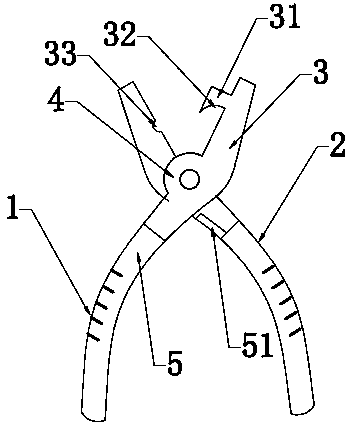
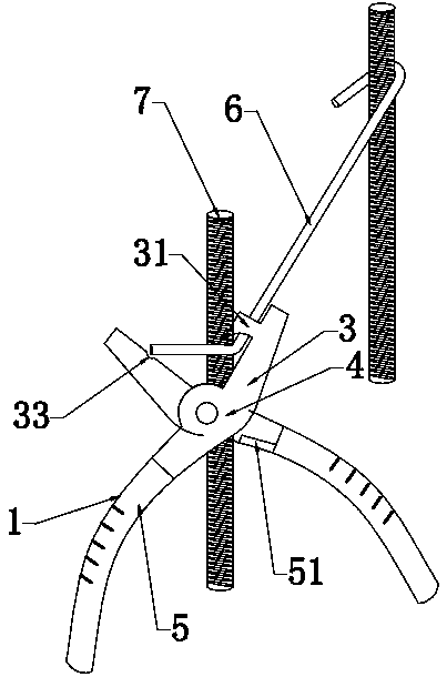
[0021] The pliers that are convenient to bend the reinforcing bar that present embodiment provides, as figure 1 , figure 2 As shown, it includes two main tongs 1 and auxiliary tongs 2 that are arranged across each other and are rotatably fixed together. The main tongs 1 and auxiliary tongs 2 are both composed of a tong head 3, a connecting part 4 and a grip handle 5 ; Inside the jaw 3 of the main tongs 1 is provided with a fastening portion 31 for holding the longitudinal rib tightly, and at the upper end of the gripping handle 5 of the auxiliary tongs 2 is provided with a gripping handle 5 upper end higher than the main tongs 1 and The limit projection 51 of the connection part 2 has a gap between the end of the limit projection 51 adjacent to the connection part 4 and the connection part when the grip handle 5 is not pulled, and the vertical distance of the gap is not Less than 2.696L (L is the distance between the main tongs 1 and the auxiliary tongs 2 adjacent to the con...

Embodiment 2

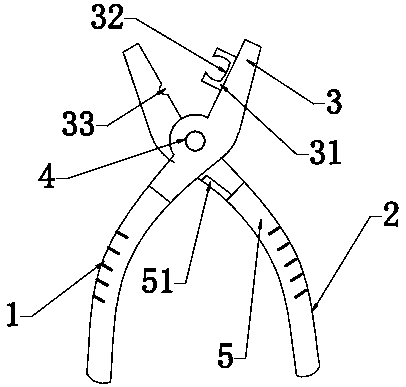
[0025] A pair of pliers for bending steel bars, such as image 3 As shown, it includes two main tongs 1 and auxiliary tongs 2 that are arranged across each other and are rotatably fixed together. The main tongs 1 and auxiliary tongs 2 are both composed of a tong head 3, a connecting part 4 and a grip handle 5 ; Inside the jaw 3 of the main tongs 1 is provided with a fastening portion 31 for holding the longitudinal rib tightly, and at the upper end of the gripping handle 5 of the auxiliary tongs 2 is provided with a gripping handle 5 upper end higher than the main tongs 1 and The limit projection 51 of the connection part 2 has a gap between the end of the limit projection 51 adjacent to the connection part 4 and the connection part when the grip handle 5 is not pulled, and the vertical distance of the gap is not Less than 2.696L (L is the distance between the main tongs 1 and the auxiliary tongs 2 adjacent to the connection part 4 when the tongs are in a closed state).

[00...


PUM


Abstract

The invention discloses a pliers facilitating bending of rebars. The pliers comprise a main plier part and a plier part arranged in mutual intersection and rotatably fixed together, and each of the main plier part and the auxiliary plier part is composed of a plier head, a connection portion and a handle. The pliers are characterized in that the inner side of the plier head of the main plier part is provided with a fastening portion used for holding a longitudinal bar, the upper end of the handle of the auxiliary plier part is provided with a limiter protrusion that is higher than the upper end of the handle of the main plier part and the connection portion, a gap is formed between the end of the limiter protrusion close to the connection portion and the connection portion when the corresponding handle is not moved, and the limiter protrusion abuts to the adjacent handle and stops rotate after the handle is turned by a certain angle. The pliers obtained by the invention have the advantages of simple structure, bending effectiveness and high bending precision.

Description

technical field [0001] The invention belongs to the field of stirrup installation, in particular to a pair of pliers for bending steel bars. Background technique [0002] During building construction, it is necessary to make a large number of steel cages to form the load-bearing parts of the building. Generally, the reinforcement cage is composed of upper longitudinal bars, lower longitudinal bars arranged up and down, and stirrups for connecting the upper longitudinal bars and the lower longitudinal bars. During the installation process, in order to meet the anti-seismic requirements, both ends of the single-leg hoop need to be processed into a hook shape, and the hook needs to be around 135°. When both ends of the single-limb hoop are processed into a hook shape, it is not convenient to fix the single-limb hoop on the corresponding vertical bar on the spot. Therefore, in actual operation, one end of the single-limb hoop needs to be processed into a hook shape of about 13...

Claims


Application Information

Patent Timeline
Patent Type & Authority Applications(China)
IPC IPC(8): B21F1/00
CPCB21F1/002
Inventor 李光顺朱坤
Owner CHINA METALLURGICAL CONSTR ENG GRP
Why Eureka
Try Eureka