
How to use the automatic dehydration device of the oil storage tank

A technology for dehydration devices and oil storage tanks, applied in separation methods, chemical instruments and methods, packaging, etc., can solve problems such as high work intensity, difficult installation, and inaccurate dehydration, so as to improve oil inlet efficiency and avoid liquid level confusion , The effect of improving the dehydration efficiency

Inactive Publication Date: 2018-05-01
WUHAN INSTITUTE OF TECHNOLOGY +1
View PDF7 Cites 0 Cited by
  • Summary
  • Abstract
  • Description
  • Claims
  • Application Information

AI Technical Summary

Problems solved by technology

[0003] (1) Open the valve on the drain pipe, manually observe the discharged liquid and close the valve immediately when there is oil - this method has high work intensity and low efficiency, and the irritating and harmful gas in the oil will endanger the health of the operator. It is difficult to monitor whether dehydration contains oil, which may easily cause dehydration accidents and cause environmental pollution
[0004] (2) Install a floating ball and a transmission mechanism in the tank. The floating ball is connected to the drain valve through the transmission mechanism. The rise and fall of the oil-water interface in the tank drives the floating ball to rise and fall. , to achieve the dehydration effect - this method has the following problems, a) the transmission mechanism is inside the tank, which is not only difficult to install but also easily damaged by oil and water; b) there is no water content feedback mechanism, the dehydration is not accurate, easy to leak oil or the dehydration is not enough
[0005] (3) Install a water content analyzer inside the tank, the water content analyzer can measure the water content, open the drain valve, and when the measured water content is zero, just close the drain valve - this method can accurately dehydrate, but due to the The variety of oil is single, the density difference between oil and water is large, and the price of the water content analyzer used is relatively high. If each oil storage tank is equipped with a water content analyzer, the cost will be very high

Method used


Image

  • How to use the automatic dehydration device of the oil storage tank
  • How to use the automatic dehydration device of the oil storage tank

Examples


Embodiment Construction

[0024] The present invention will be further described below with reference to the accompanying drawings and embodiments.

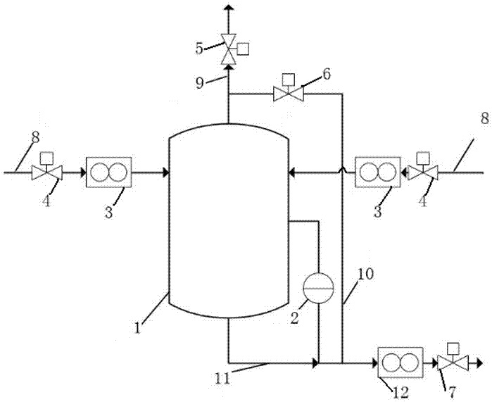
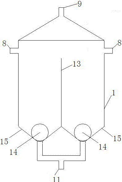
[0025] like figure 1 As shown, an automatic dehydration device for an oil storage tank includes a differential pressure gauge 2 and a sealed tank 1. The tank 1 is provided with a floating ball 14 with a density between oil and water, and a conical groove 15 at the bottom. , the bottom of the float ball 14 can be completely fitted with the conical groove 15, the bottom of the conical groove 15 is connected with the drain pipe 11, the top of the tank body 1 is connected with the oil inlet pipe 8 and the oil return pipe 9 respectively, the drain pipe 11, the oil inlet pipe 8 and the return pipe The oil pipe 9 is provided with valves (respectively 7, 4, and 5), the drain pipe 11 and the oil inlet pipe 8 are also provided with flow meters (respectively 12 and 3), and the two measuring ends of the differential pressure gauge 2 are located at Inside the tank 1 ...


PUM


Abstract

The invention relates to an automatic dewatering device of an oil storage tank and an application method of the automatic dewatering device. The device comprises a differential pressure gauge and a sealed tank body, wherein the tank body is internally provided with a floating ball with the density between densities of oil and water and a tapered groove is formed in the bottom of the tank body; the bottom of the floating ball can be completely matched with the tapered groove; the bottom of the tapered groove is communicated with a water drainage pipe; the top of the tank body is communicated with an oil inlet pipe and an oil returning pipe respectively; valves are arranged on the water drainage pipe, the oil inlet pipe and the oil returning pipe respectively; a flow meter is arranged on each of the water drainage pipe and the oil inlet pipe; and two measuring ends of the differential pressure gauge are located in the tank body and the water drainage pipe respectively. The device has good reliability, accuracy in dewatering and low cost.

Description

technical field [0001] The invention belongs to the technical field of dehydration of oil storage tanks, and in particular relates to an automatic dehydration device for oil storage tanks and a method for using the same. Background technique [0002] There will be more or less a certain amount of water in the oil storage tank, so the oil storage tank needs to be dehydrated before the oil is discharged. At present, there are three dehydration methods for the oil storage tank: [0003] (1) Open the valve on the drain pipe, manually observe the discharged liquid, and close the valve immediately when oil appears - this method has high work intensity and low efficiency, and the irritating and harmful gases in the oil will endanger the health of the operator. It is difficult to monitor whether the dehydration contains oil, which may easily lead to the accident of dehydration and oil leakage, resulting in environmental pollution. [0004] (2) A float ball and a transmission mechan...

Claims


Application Information

Patent Timeline
Patent Type & Authority Patents(China)
IPC IPC(8): B01D17/032B65D90/48B65D88/54
CPCB65D88/54B65D90/48
Inventor 喻九阳高海徐建民郑小涛林纬王成刚
Owner WUHAN INSTITUTE OF TECHNOLOGY
Learn More