Staggered feeding mechanism

A feeding mechanism and feeding technology, used in conveyors, vibrating conveyors, conveyor objects, etc., can solve the problems of jamming, inability to dislocate screws and send them to the corresponding, and achieve the effect of preventing jamming

Inactive Publication Date: 2016-04-20
BOZHON PRECISION IND TECH CO LTD
View PDF9 Cites 18 Cited by
  • Summary
  • Abstract
  • Description
  • Claims
  • Application Information

AI Technical Summary

Problems solved by technology

[0002] In the prior art, during the screw feeding process, the vibrating plate is generally used to vibrate the material, and the material is sent from the vibrating track for feeding. The screws cannot be dislocated one by one to the corresponding position, which has a certain impact o

Method used


Image

  • Staggered feeding mechanism
  • Staggered feeding mechanism
  • Staggered feeding mechanism

Examples


Embodiment Construction

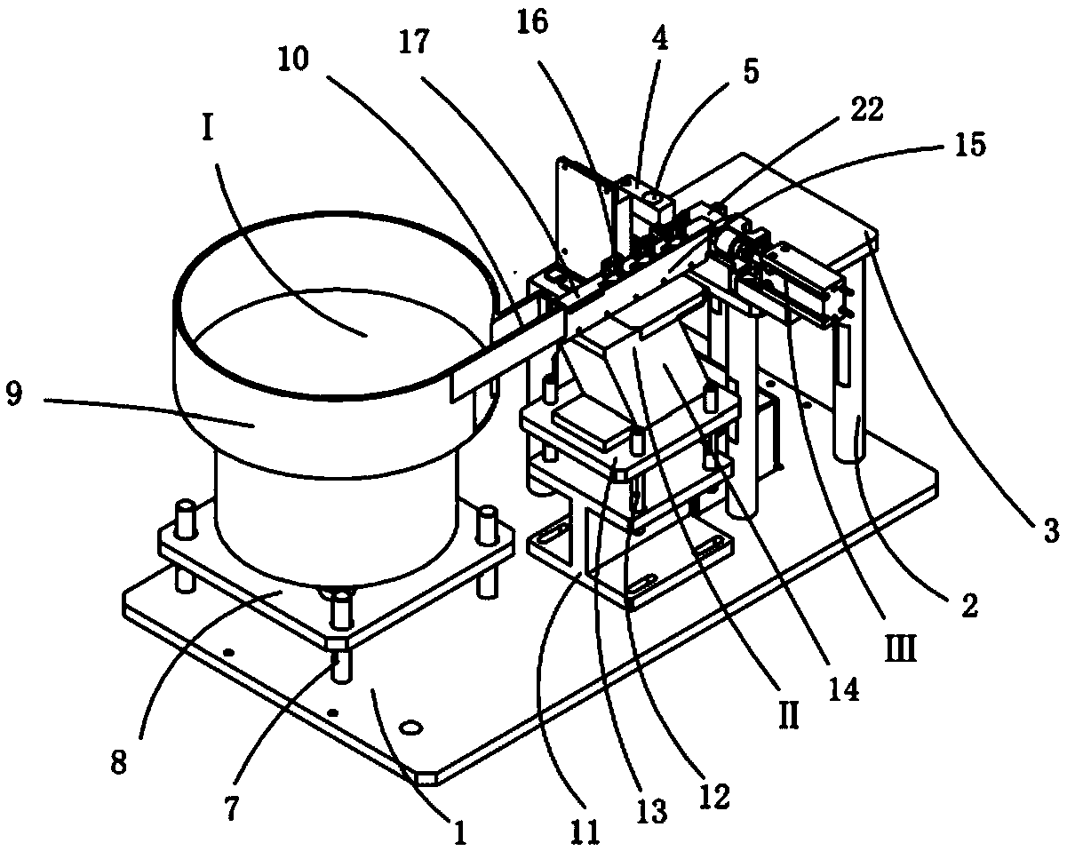
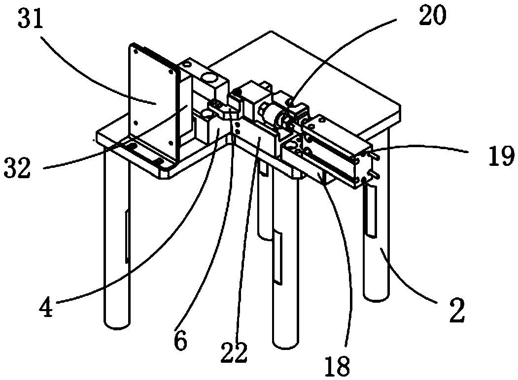
[0021] Examples, see attached Figure 1~5 , a dislocation feeding mechanism, including a bottom plate 1, a feeding assembly I is installed on the bottom plate, a direct vibration assembly II is installed on the right side of the feeding assembly on the bottom plate, the feeding track of the feeding assembly is connected to the direct vibration assembly The direct vibration track is connected; the distribution base plate 3 is installed on the base plate through the distribution support 2, and there are four distribution supports, and the distribution base plate is installed on the four distribution supports; the dislocation base plate is installed on the distribution base plate. Feeding component III; a blanking base 4 is installed on the distribution bottom plate, a through hole 5 is provided on the blanking base, and a screw supporting block 6 is installed on the front side of the blanking base.

[0022] The feeding assembly includes a vibrating disc screw 7, a vibrating disc...


PUM


Abstract

The invention relates to a staggered feeding mechanism. A feeding component and a direct vibration component are mounted on a bottom plate, and a material feeding track of the feeding component is communicated with a direct vibration track of the direct vibration component; a material slitting bottom plate is mounted on the bottom plate through material spitting pillars; a staggered feeding component is mounted on the material slitting bottom plate; a blanking base is mounted on the material spitting bottom plate, and a screw butting block is mounted on the front side of the blanking base; a staggered cylinder fixing block and a staggered slider groove are formed in the material slitting bottom plate, a staggered cylinder is mounted on the staggered cylinder fixing block, and a staggered slider is mounted inside the staggered slider groove in a matched manner; the front end of the piston rod of the staggered cylinder is connected with the staggered slider through the staggered cylinder joint; a half-cylinder groove used for positioning screws is formed in the left rear side of the staggered slider, and an avoidance notch for preventing material blockage is formed in the front side inside the screw butting block. The feeding component is used for supplying material continually; and the staggered cylinder drives the staggered slider to move, and under the effect of the screw butting block, screws are staggered on by one and moved to adsorption positions.

Description

Technical field: [0001] The invention relates to the field of screw feeding equipment, and more specifically relates to a screw feeding mechanism that staggers screws one by one and moves them to positions to be adsorbed. Background technique: [0002] In the prior art, during the screw feeding process, the vibrating plate is generally used to vibrate the material, and the material is sent from the vibrating track for feeding. The screws cannot be dislocated one by one to the corresponding position, which has a certain impact on the subsequent use of the screw, and the direct vibration Sometimes there will be material jamming after discharging, so it is necessary to design a screw feeding mechanism that staggers the screws one by one and moves them to the position to be adsorbed to improve the locking effect. Invention content: [0003] The purpose of the present invention is to provide a dislocation feeding mechanism for the deficiencies of the prior art. The dislocation ...

Claims


Application Information

Patent Timeline
IPC IPC(8): B65G47/14B65G27/02
CPCB65G47/1421B65G27/02
Inventor 吕绍林杨愉强吴小平姜超盛少雄
Owner BOZHON PRECISION IND TECH CO LTD
Why Eureka
Try Eureka