
Knitting machine

A technology of textile machines and knitting discs, applied in the field of knitting machines, can solve the problems such as the instable transmission of rotating parts, and achieve the effects of good motion coordination effect, small overall volume and improved quality.

Inactive Publication Date: 2016-04-20
ZHOUSHAN RUIJIAN MACHINERY CO LTD
View PDF6 Cites 2 Cited by
  • Summary
  • Abstract
  • Description
  • Claims
  • Application Information

AI Technical Summary

Problems solved by technology

However, the spinning machine is driven by a transmission belt, and the transmission of its rotating parts is not stable enough. Therefore, the structure of the device needs to be further improved.

Method used


Image

  • Knitting machine
  • Knitting machine
  • Knitting machine

Examples


Embodiment Construction

[0029] The present invention will be further described in detail below in conjunction with the accompanying drawings and embodiments.

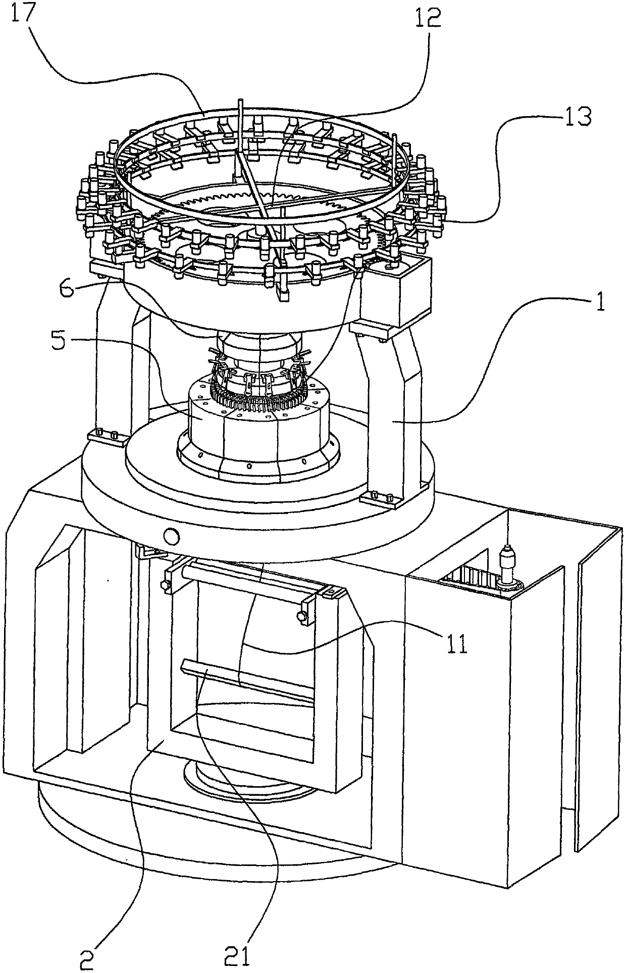
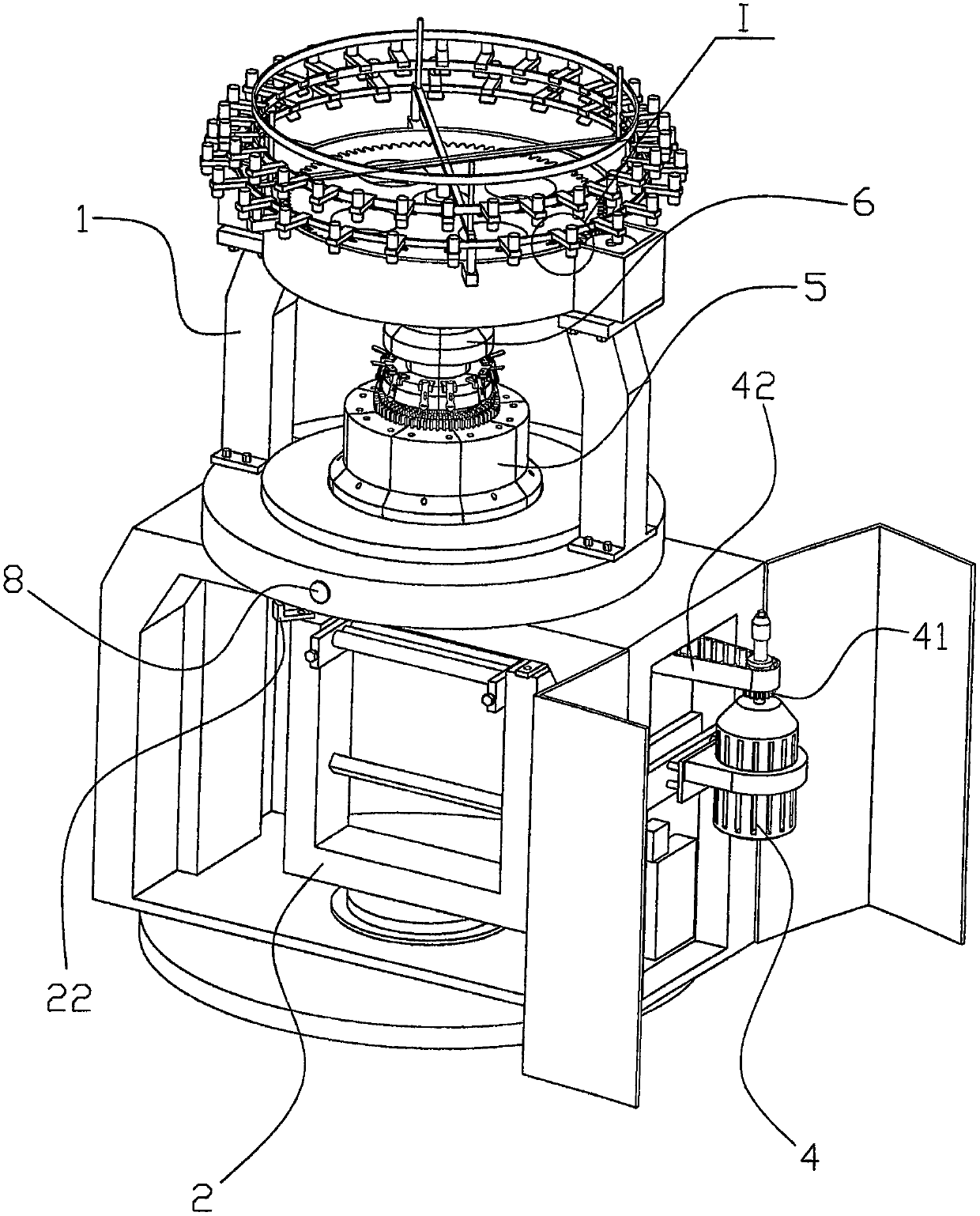
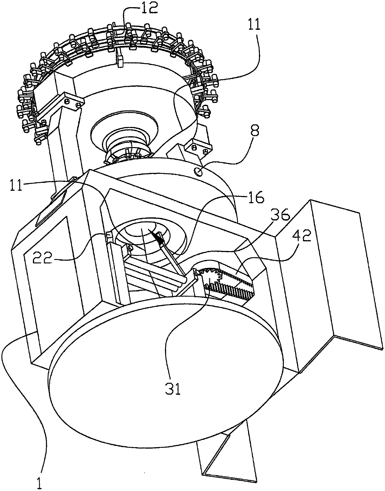
[0030] Such as Figure 1 to Figure 14As shown, the textile machine of this embodiment includes a frame body 1, and the frame body 1 is provided with a thread supply part, a knitting part and a finished cloth collection part, and the textile thread 11 enters the knitting part from the thread supply part and is connected to the knitting part. On the knitting needles, the textile thread 11 after knitting and knitting the finished cloth is wound on the winding roller 21 of the finished cloth collection part, and the knitting part is driven by the drive motor 4 and is rotatably arranged in the middle of the frame body 1. The part includes a first rotating gear 31, the first rotating gear 31 can be driven by the drive motor 4 to be rotatably arranged on the rotating shaft 3, and the said rotating shaft 3 can be rotatably arranged on the frame body 1...


PUM


Abstract

The invention provides a knitting machine which comprises a frame body. A thread supply part, a knitting part and a finished cloth product collecting part are arranged on the frame body. The knitting part comprises a first rotating gear. The first rotating gear is driven by a motor and arranged on a rotating shaft in a rotating mode. The rotating shaft is arranged on the frame body in a rotating mode. The first rotating gear is meshed with a rotating disc. The rotating disc is provided with a vertical thread knitting disc. Vertical knitting needles are arranged in a vertical knitting groove. The rotating shaft is provided with a second rotating gear meshed with a third rotating gear. The third rotating gear is connected with a transverse thread knitting disc. Transverse knitting needles can be arranged in a transverse knitting groove in the mode of being capable of moving left and right. The thread supply part comprises a thread supply support which is provided with a thread conveying roller. Spinning threads enter the knitting part from the thread conveying roller and are hooked and connected to the vertical knitting needles or the transverse knitting needles. The finished cloth product collecting part comprises a rotating support arranged on the lower portion of the frame body. The spinning threads extend into the rotating support and are wound around a winding roller. The knitting machine has the advantages of being small in occupied space and stable in transmission.

Description

technical field [0001] The invention relates to the field of textile equipment, in particular to a knitting machine with a firm and stable transmission structure. Background technique [0002] An existing Chinese invention patent No. CN200910134855.2 titled "Spinning Machine with Independent Spindle Drive" discloses a spindle device for a textile machine, which includes a rotatably driven spindle top, a spindle bearing housing, a motor and a motor housing housing the motor, the spindle top has a tube sleeve and a spindle bar, the spindle bearing housing rotatably supports the spindle bar and has upper and lower bearings, the motor drives the spindle top and includes A stator and a rotor are arranged separated from each other by an air gap. The invention differs in that the stator is non-rotatably connected to the motor housing, the rotor is non-rotatably connected to a connecting part on top of the spindle, and the lower part of the spindle bearing housing in which the spin...

Claims


Application Information

Patent Timeline
Patent Type & Authority Applications(China)
IPC IPC(8): D04B9/02D04B15/94D04B15/18
CPCD04B9/02D04B15/18D04B15/94
Inventor 胡建军
Owner ZHOUSHAN RUIJIAN MACHINERY CO LTD
Learn More