Dewatering-type mini washer
A technology of a washer and a washing tub, which is applied to washing devices, other washing machines, washing machines with containers, etc., can solve the problems of large volume, poor stability, and inability to set up a dehydration structure, and achieves large volume, stable use, and small volume. Effect
- Summary
- Abstract
- Description
- Claims
- Application Information
AI Technical Summary
Problems solved by technology
Method used
Image
Examples
Embodiment 1
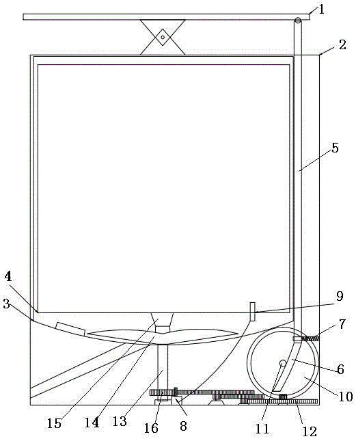
[0025] Such as figure 1 As shown, the dehydration mini scrubber of the present invention, the dehydration mini scrubber, includes a washing bucket 3, a rotating shaft 13 running through the bottom of the washing bucket 3, and a water stirring device 14 is arranged inside the washing bucket 3, and the rotating shaft 13 is connected to the water stirring device 14 , the rotating shaft 13 is connected with a driving device, and in the dehydration state: the dehydration bucket 3 is provided with a dehydration bucket 4, the dehydration bucket 4 is coaxially arranged with the water stirring device 14, and the center of the water stirring device 14 adopts a directional rotating part 15 and a dehydration bucket 4 The center of the bucket bottom is connected, and the driving device drives the rotating shaft 13 and drives the water stirring device 14 to rotate positively and negatively, and simultaneously drives the dehydration bucket 4 to rotate directionally.
[0026] The design princ...
Embodiment 2
[0029] The difference between this embodiment and Embodiment 1 is that the driving device is a pedal-type driving device, and the pedal-type driving device includes a lever-type pedal 1 located on the cover plate, and one end of the pedal 1 is connected with a force transmission straight rod 5, There is a gap between the inner wall of the housing and the outer wall of the washing tub 3, and the straight force transmission rod 5 is inserted vertically downward into the gap, and a spring limiter 7 is installed on the inner wall of the housing, and the spring limiter 7 is socketed with the straight force transmission rod 5 The end of the force transmission straight rod 5 away from the pedal 1 is connected with a rack 6, and the rack 6 meshes with the shaft gear 16 arranged on the drive shaft 13 directly or through a transmission assembly.
[0030] The design principle of the above structure is: the pedal of the traditional structure is a bicycle-style pedal drive or a reciprocatin...
Embodiment 3
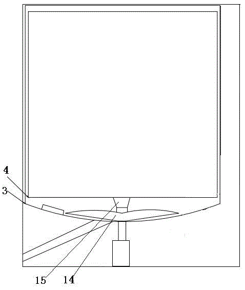
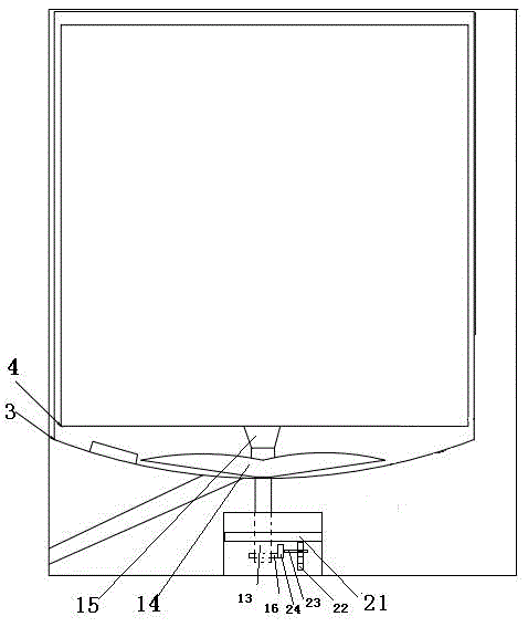
[0039] The difference between this embodiment and embodiment 2 is: as figure 2 As shown, the driving device is a motor.
PUM
 Abstract
Description
Claims
Application Information
 - R&D
- Intellectual Property
- Life Sciences
- Materials
- Tech Scout
- Unparalleled Data Quality
- Higher Quality Content
- 60% Fewer Hallucinations
Browse by: Latest US Patents, China's latest patents, Technical Efficacy Thesaurus, Application Domain, Technology Topic, Popular Technical Reports.
© 2025 PatSnap. All rights reserved.Legal|Privacy policy|Modern Slavery Act Transparency Statement|Sitemap|About US| Contact US: help@patsnap.com


