Tongue and groove connecting structure of building formwork
A technology for building templates and connecting structures, which is applied to the connection parts of formwork/formwork/work frame, building structure, formwork/formwork components, etc., which can solve the problems of high connection strength and fast connection speed, and ensure the connection Strength, effect of achieving connection strength, fast connection
- Summary
- Abstract
- Description
- Claims
- Application Information
AI Technical Summary
Problems solved by technology
Method used
Image

Examples
Embodiment 1
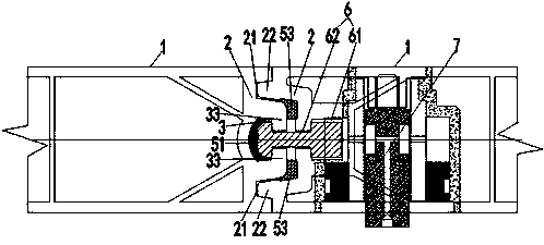
[0046] like figure 1 and 2 As shown, the tongue-and-groove connection structure of the building formwork described in this embodiment has a pouring surface and an outer surface opposite to the pouring side plate; it is formed on the edge 2 between the pouring surface and the outer measuring surface There is a tongue-and-groove structure; the tongue-and-groove structure includes molding on the edge 2, the notch 31 faces the locking groove 3 parallel to the pouring surface, and a locking device arranged on the edge 2 of the adjacent template 1; the The locking device has a locking piece 4 that is relatively movably connected to the adjacent template 1 and is suitable for being embedded in the locking groove 3. The locking piece 4 cooperates with the locking groove 3 to prevent two adjacent templates 1 from interacting with each other. separate. In this embodiment, the setting of the locking member 4 and the locking groove 3 can not only realize the quick connection between the...
Embodiment 2
[0062] As a convertible implementation mode, the difference between this embodiment and embodiment 1 is:
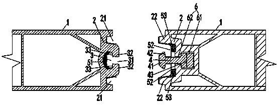
[0063] like image 3 As shown, the locking member 4 is rotatably connected to the adjacent template by a pivot set parallel to the direction of the edge 2; the locking member 4 is rotated so that the locking head 41 and the locking surface Lamination. That is, in this embodiment, the locking member 4 can be mounted on the adjacent template 1 on the pivot, and it can rotate around the pivot, so that the locking head 41 is pressed against the locking surface. combined, thereby preventing the separation of two adjacent templates 1
[0064] In this embodiment, the locking members 4 rotate in opposite directions and are arranged in pairs, and the partial pressures in the direction perpendicular to the pouring surface cancel each other when pressed. Specific as image 3 As shown, the locking groove is provided with an intermediate T-shaped portion, the two lateral inner end...
Embodiment 3
[0066] As a convertible implementation mode, the differences between this embodiment and embodiment 1 are:
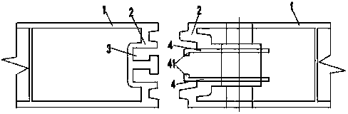
[0067] like Figure 4 and Figure 5 As shown, the locking groove 3 is at least one transverse groove arranged alternately along the extending direction of the edge 2; the locking member 4 is a locking hook arranged alternately along the extending direction of the edge 2 and corresponding to the transverse groove; Each of the locking hooks is rotatably connected to the adjacent formwork by a pivot perpendicular to the pouring surface. In the case of more than two locking hooks, a linkage rod keeps each of the locking hooks linked. . In this embodiment, the locking member 4 is set as a locking hook, and when two adjacent templates 1 are connected to each other, the locking hook rotates and engages with the transverse groove, thereby connecting the two templates 1 In the case of a plurality of locking hooks, the same linkage rod is used to drive the locking hooks to eng...
PUM
 Abstract
Description
Claims
Application Information