Control valve and hydraulic control system of loading machine

A control valve and hydraulic oil technology, applied in the hydraulic field, can solve problems such as poor stability, and achieve the effects of improving stability, improving comfort, and strong versatility

Active Publication Date: 2016-04-20
GUANGXI LIUGONG MASCH CO LTD
View PDF5 Cites 5 Cited by
  • Summary
  • Abstract
  • Description
  • Claims
  • Application Information

AI Technical Summary

Problems solved by technology

[0003] The technical problem to be solved by the present invention is to provide a control valve capable of improving the stability of the ultra-lon

Method used


Image

  • Control valve and hydraulic control system of loading machine
  • Control valve and hydraulic control system of loading machine

Examples


Embodiment Construction

[0016] The specific implementation will be described below in conjunction with the accompanying drawings.

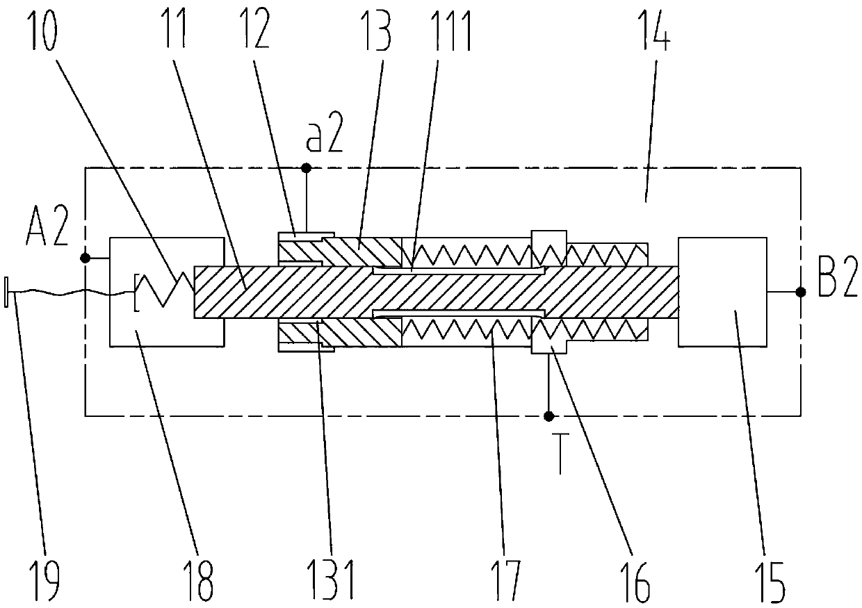
[0017] Such as figure 1 As shown, the control valve in this embodiment includes a valve body 14, a valve core 11, and a valve sleeve 13. The valve body 14 is provided with an oil return T port, a working A2 port, a working B2 port, a pilot a2 port, and a valve core 11 is located in the valve body 14, the left end and the right end of the valve core 11 are slidingly fitted with the valve body 14 respectively, an intermediate chamber is formed between the middle part of the valve core 11 and the valve body 14, and a first cavity 18 is arranged in the valve body 14 And the fourth cavity 15, the first cavity 18 is located at the left end of the spool 11, the first cavity 18 communicates with the working A2 port and the hydraulic oil in the first cavity 18 acts on the left end of the spool 11, the fourth cavity 15 is located at the spool 11, the fourth chamber 15 communicate...


PUM


Abstract

The invention relates to a hydraulic control valve, aims to solve the problem that the floating descent stability of a movable arm of an existing ultra-long arm loading machine is reduced, and provides a control valve. The control valve comprises a valve element, wherein the valve element is located in a valve body. A first cavity and a fourth cavity are formed in the valve body, the first cavity is communicated with a working opening A2, hydraulic oil in the first cavity acts on the left end of the valve element, the fourth cavity is communicated with a working opening B2, and hydraulic oil in the fourth cavity acts on the right end of the valve element. A valve sleeve is located in a middle cavity and arranged on the valve element in a sleeving mode, and the middle cavity is divided by the valve sleeve into a second cavity and a third cavity. A valve element spring which acts on the left end of the valve element is arranged in the first cavity, and a valve sleeve spring which acts on the right end of the valve sleeve is arranged in the third cavity. An oil return opening T is communicated with the third cavity, and a guide opening a2 is communicated with the second cavity. An oil drain channel which is used for communicating the second cavity with the third cavity in the working process and being closed in the initial state is arranged between the valve element and the valve sleeve. According to the invention, the initial state means the state of being free of floating descent, and the working state means the state of floating descent.

Description

technical field [0001] The invention relates to hydraulic technology, more specifically, to a hydraulic control valve and a loader hydraulic control system with the control valve. Background technique [0002] Loaders are widely used in modern construction. In order to meet various special working conditions in response to market demand, some loaders are equipped with super-long booms, but the stability of super-long boom loaders is worse than that of ordinary boom loaders. During the floating and descending process, the whole machine shakes greatly, and the driver's operating comfort is not high. Therefore, it is very important to make the stability performance of the ultra-long boom loader reach the effect of the ordinary boom. Contents of the invention [0003] The technical problem to be solved by the present invention is to provide a control valve capable of improving the stability of the ultra-long boom loader during the floating and lowering process and to provide ...

Claims


Application Information

Patent Timeline
IPC IPC(8): F15B13/06F15B11/16E02F3/42E02F9/22
CPCE02F3/42E02F3/422E02F9/22E02F9/2207F15B13/06F15B2211/4053
Inventor 范武德谭艳辉王允梁振国武元刘万天
Owner GUANGXI LIUGONG MASCH CO LTD
Why Eureka
Try Eureka