A Continuous Position Recognition Device for Microscope

A technology for identifying devices and microscopes, applied in the field of microscopes, can solve the problem of Hall sensors not being able to sense signals, etc., and achieve the effects of being unaffected by distance, not limited by size, and having high signal sensitivity

Active Publication Date: 2018-10-02
MOTIC CHINA GRP CO LTD
View PDF12 Cites 0 Cited by
  • Summary
  • Abstract
  • Description
  • Claims
  • Application Information

AI Technical Summary

Problems solved by technology

[0004] However, this technology has certain limitations. This technology is limited by the size of the microscope system. The number of magnet groups installed on the working position switching device is always limited. When the number of working positions to be identified exceeds this limited number number, the existing location recognition devices cannot meet the requirements
In addition, the existing position recognition device has relatively strict requirements on the distance between the magnet group and the Hall sensor. If the distance exceeds this requirement, the Hall sensor will not sense the signal.
This also brings more constraints to the design of the microscope system

Method used


Image

  • A Continuous Position Recognition Device for Microscope
  • A Continuous Position Recognition Device for Microscope

Examples


Embodiment 1

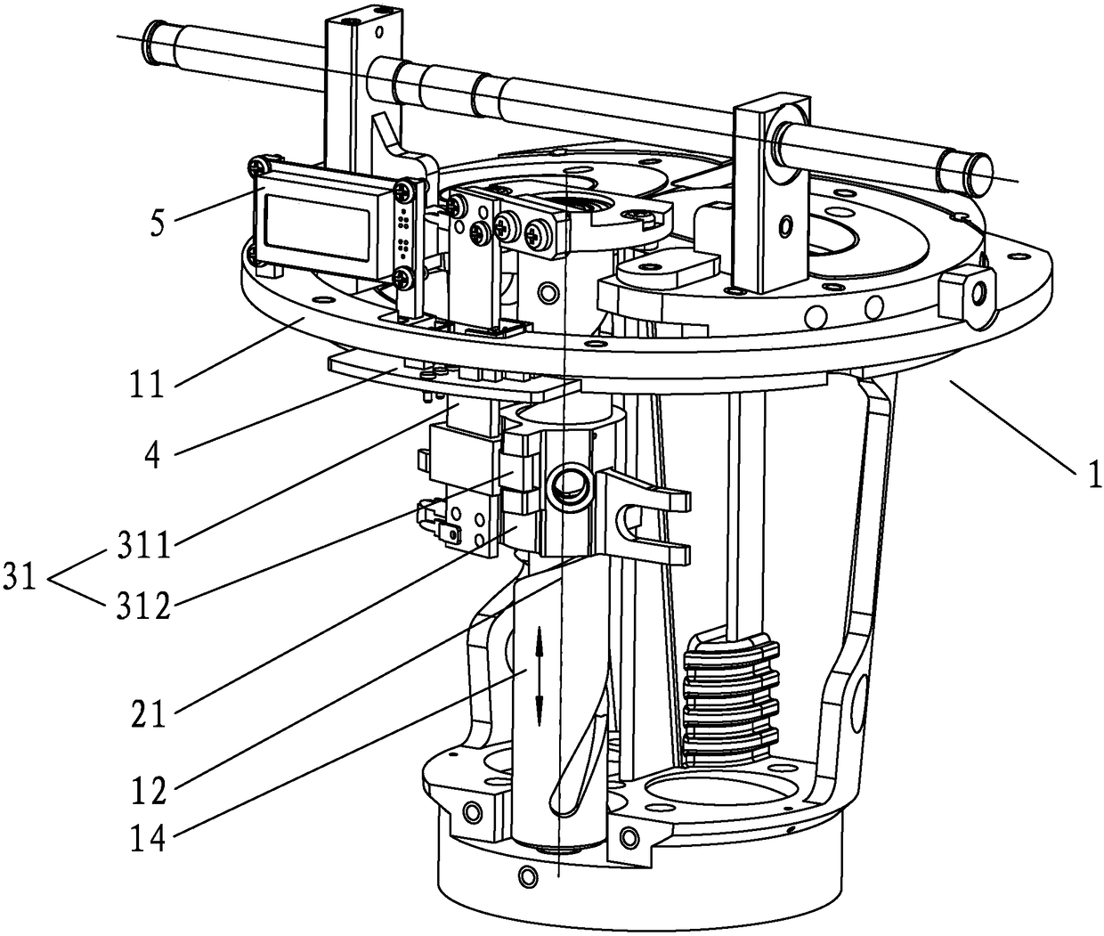
[0024] like figure 1 As shown, a continuous position recognition device for a microscope includes a frame 1 , a working position switching mechanism, a potentiometer, a control circuit 4 and an additional display device 5 . The working position switching mechanism in this embodiment is a zoom guide sleeve 21, the potentiometer is a straight slide potentiometer 31, and the additional display device 5 is a liquid crystal display module.

[0025] The main frame includes a horizontally arranged main board 11 and a vertical shaft 14 vertically fixed on the lower surface of the main board 11 . The variable magnification guide sleeve 21 is movably connected with the vertical shaft and can perform continuous linear movement along a vertical axis 12 of the vertical shaft 14 . The straight-slide potentiometer 31 includes a straight-slide potentiometer body 311 and an intermediate tap slide bar 312. The straight-slide potentiometer main body 311 is vertically installed on the lower surf...

Embodiment 2

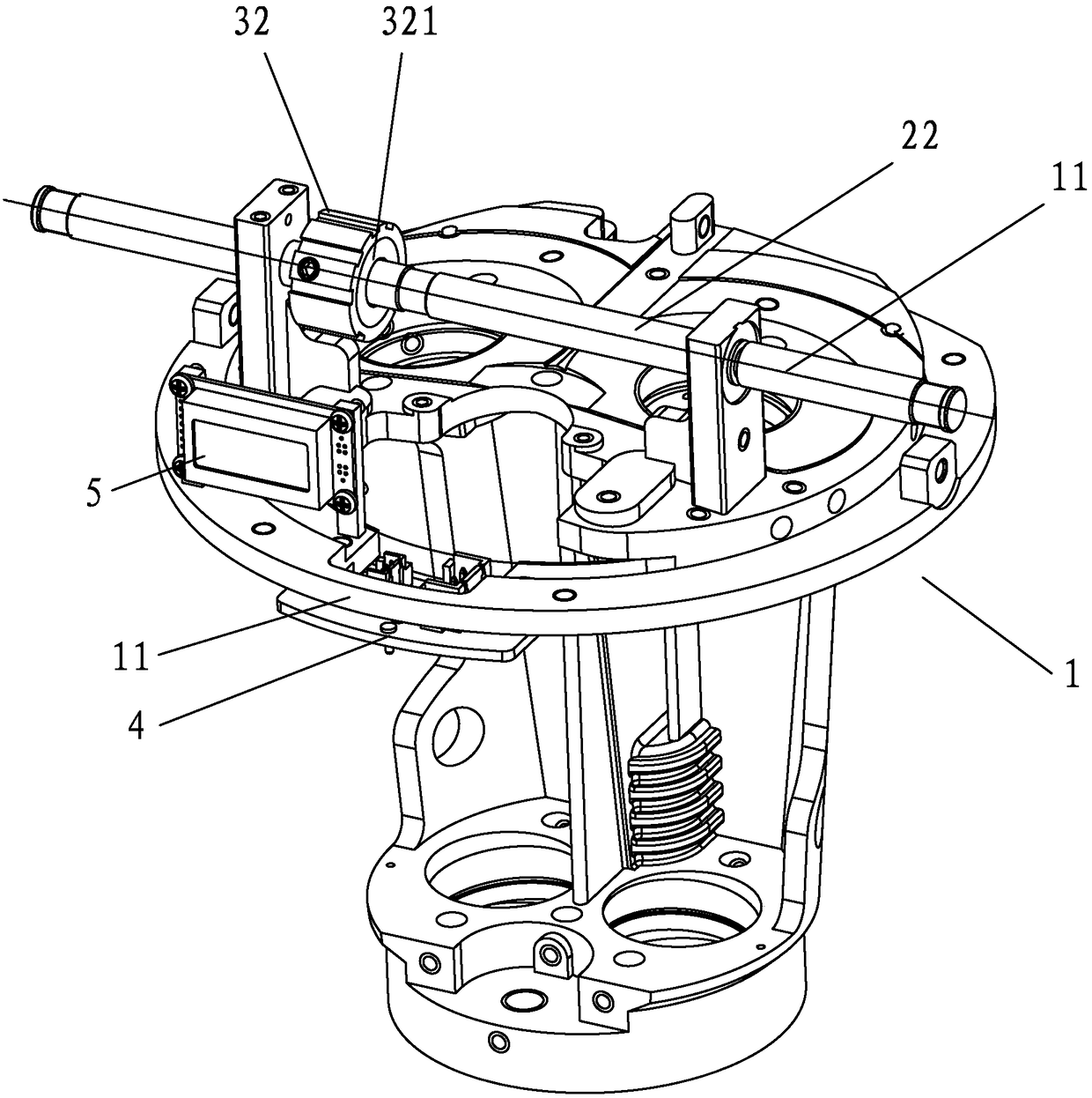
[0029] like figure 2 As shown, a continuous position recognition device for a microscope includes a frame 1 , a working position switching mechanism, a potentiometer, a control circuit 4 and an additional display device 5 . The working position switching mechanism of this embodiment is the zoom handwheel shaft 22, the potentiometer is a rotary potentiometer 32, and the additional display device 5 is an LED.

[0030] The main frame includes a horizontally arranged main board 11 . The zoom handwheel shaft 22 is horizontally installed on the bracket on the upper surface of the main board 11 , and the zoom handwheel shaft 22 can perform continuous linear rotation along a horizontal axis 13 of the zoom handwheel shaft 22 . The middle tap 321 of the rotary potentiometer 32 is coaxially fixedly connected with the zoom handwheel shaft 22 , and the middle tap 321 of the rotary potentiometer 32 can perform synchronous and continuous rotational movement with the zoom handwheel shaft 22...

Embodiment 3

[0034] In this embodiment, on the basis of Embodiment 1, the control circuit 4 is connected to the light source brightness control unit of the microscope. Set different light source brightness for different working positions; when the microscope observer switches to a certain working position of the continuous zoom microscope for the first time, the brightness of the lighting source is adjusted according to the magnification requirements of the working position. After the adjustment, the control The circuit will immediately store the brightness of this position in the memory according to the change of the resistance value of the potentiometer. The stored brightness of the working position. That is, when the working position of the working position switching mechanism changes, the control circuit (4) can automatically adjust the brightness of the light source according to the brightness data of the light source stored in the memory.


PUM


Abstract

The invention relates to the field of microscopes and discloses a microscope continuous position identification device. The device comprises a machine frame, a working position switching mechanism, a potentiometer and a control circuit, wherein the working position switching mechanism is connected with the machine frame in a pivoting mode and can make continuous linear motion or continuous rotational motion along a certain axis on the machine frame; the potentiometer comprises a center tap, the center tap is fixed on the working position switching mechanism and can move synchronous with the working positioning switching mechanism, and each instant working position of the working position switching mechanism corresponds to a unique potentiometer resistance variable quantity; the control circuit is connected with the potentiometer, a memory is arranged in the control circuit, and the information of the correspondence between the potentiometer resistance variable quantities and the working positions of the working position switching mechanism is stored in the memory. According to the device, a large number of working positions can be identified, dimensional limitation is avoided, and the potentiometer is highly sensitive to signals without being affected by distance.

Description

technical field [0001] The invention relates to the field of microscopes, in particular to a continuous position recognition device for a microscope. Background technique [0002] In microscopic observation, according to observation needs, sometimes a microscope with continuous zoom is used. For the marking of the magnification of the continuous zoom microscope, the usual practice is to print the magnification mark on the zoom handwheel. Due to the limited area of ​​the zoom handwheel, the magnification that can be marked is also limited. If the observer turns the zoom handwheel to the middle position between the two magnification marks, the magnification of the microscope cannot be accurately known at this time. In order to better meet the needs of the observer, it is necessary to know and mark the current magnification of the continuous zoom microscope when the zoom handwheel is turned to any position. To this end, we need to continuously identify any working position o...

Claims


Application Information

Patent Timeline
Patent Type & Authority Patents(China)
IPC IPC(8): G02B21/32
CPCG02B21/32
Inventor 陶素华康军
Owner MOTIC CHINA GRP CO LTD
Why Eureka
Try Eureka