Method for electronic measurement

A technology of electronic measurement and measurement devices, applied in radio wave measurement systems, measurement devices, reradiation of electromagnetic waves, etc., can solve the problem that low-frequency signals do not contribute

Active Publication Date: 2007-11-28
LEICA GEOSYSTEMS AG
View PDF0 Cites 5 Cited by
  • Summary
  • Abstract
  • Description
  • Claims
  • Application Information

AI Technical Summary

Problems solved by technology

Because the time-of-flight information of these high-frequency receive pulses falls within the mixer gap, this information is not determined by heterodyne time conversion or frequency conversion, and therefore does not contribute to the low frequency signal

Method used


Image

  • Method for electronic measurement
  • Method for electronic measurement
  • Method for electronic measurement

Examples


Embodiment Construction

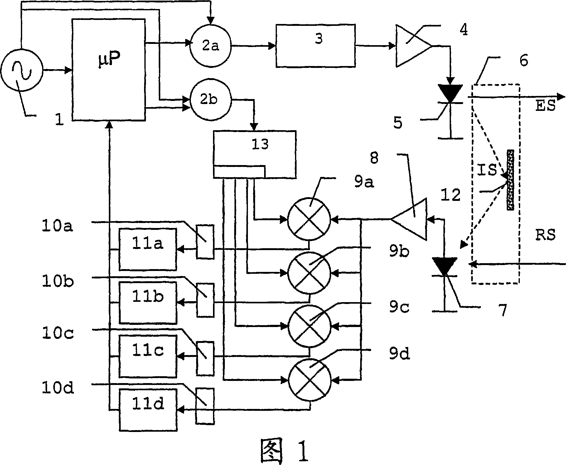
[0031] FIG. 1 shows a block diagram of an embodiment of a measuring device according to the invention based on the principle of heterodyne reception, the sensitivity of which is significantly increased compared to known phase distance measurement methods.

[0032] At the beginning of the signal train there is a quartz calibrated reference oscillator with a typical accuracy of 0.5ppm to 5ppm. In the transmit path there is a so-called direct digital frequency synthesizer 2a. Depending on programming using a microcontroller or microprocessor μP, element 2a generates the desired frequency in the range of a few kHz or MHz. Frequency converter 3 likewise corresponds to the sending channel and multiplies the frequency to a higher range, resulting in the measurement frequency F 1 . In addition, frequency converter 3 also acts as a filter and ensures the purity of the spectral signal. For coarse ranging, similar to the case of phase meters, a plurality of frequencies F are transmitt...


PUM


Abstract

The present invention provides a method for electronic measurement. According to the invention, the sensitivity of a method for electronic measurement may be improved, carried out by the principle of heterodyne reception with the steps of broadcast of pulsed electromagnetic radiation (ES) with at least one pulse repetition frequency, reception of back-scattered radiation (RS), whereby the back-scattered radiation (RS) is converted into a received signal, mixing of the received signals, determination of at least one time parameter from the at least one output signal, whereby on mixing the received signals at least two pulsed mixed signals are mixed to give at least two output signals and the at least two mixed signals are phase-shifted relative to each other.

Description

technical field [0001] The invention relates to an electronic measuring method based on the heterodyne reception principle according to the preamble of claim 1 , a measuring device according to the preamble of claim 10 , and a computer program product. Background technique [0002] In the field of electronic measurement methods, various principles and methods have been disclosed in which, according to the principle of heterodyne reception, high-frequency signals are down-converted to low-frequency signals by non-linear superposition with mixing signals for evaluation. In both heterodyne receivers and homodyne receivers there are mixers operating in order to convert the input signal to another frequency range. In this case, different mixing circuits are applied depending on the type of receiver, and the differences between these mixing circuits should be represented and evaluated qualitatively. [0003] In the special case of homodyne reception, the mixing signal from the lo...

Claims


Application Information

Patent Timeline
Patent Type & Authority Applications(China)
IPC IPC(8): G01S7/486G01S17/10
CPCG01S17/10G01S7/486G01S17/36
Inventor 保罗·本茨于尔格·欣德林马丁·德-朗格
Owner LEICA GEOSYSTEMS AG
Why Eureka
Try Eureka