A diffractive optical element

A diffractive optical element and laser technology, applied in optical elements, optics, instruments, etc., can solve the problems of large manufacturing error, expensive high-precision equipment, affecting the use of diffractive optical elements, etc., to achieve the effect of power compensation

Active Publication Date: 2020-07-10
无锡奥普顿光电子有限公司
View PDF2 Cites 1 Cited by
  • Summary
  • Abstract
  • Description
  • Claims
  • Application Information

AI Technical Summary

Problems solved by technology

However, when the precision of the manufacturing equipment is low, that is, when the size of the microstructure of the diffractive optical element is smaller than the resolution of the manufacturing machine, the manufacturing error is large, and when the obtained diffractive optical element splits the light, the power of the sub-beams is inconsistent with the expected power. A common error is that in the output matrix sub-beams, the power of the 2 beams along one diagonal is greater than the power of the 2 beams along the other diagonal (such as figure 1 shown), this result strongly affects the use of diffractive optical elements
[0006] Because high-precision equipment is expensive and cannot be widely used, most manufacturers of diffractive optical elements still use relatively low-precision manufacturing equipment. Therefore, the diffractive optical elements they produce have the above-mentioned problems

Method used


Image

  • A diffractive optical element
  • A diffractive optical element
  • A diffractive optical element

Examples


Embodiment Construction

[0031] combine Figure 2 to Figure 17 , which describes a specific embodiment of the present invention in detail, but does not limit the claims of the present invention in any way.

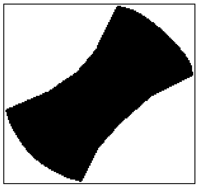
[0032] Design a diffractive optical element that conforms to 0 / c×π binary distribution, and its phase distribution is Φ(i,j), where i, j represent the position of the diffractive optical element in each cycle, i=1...n , j=1...m, such as figure 2 As shown, it is Φ(i,j) of a cycle.

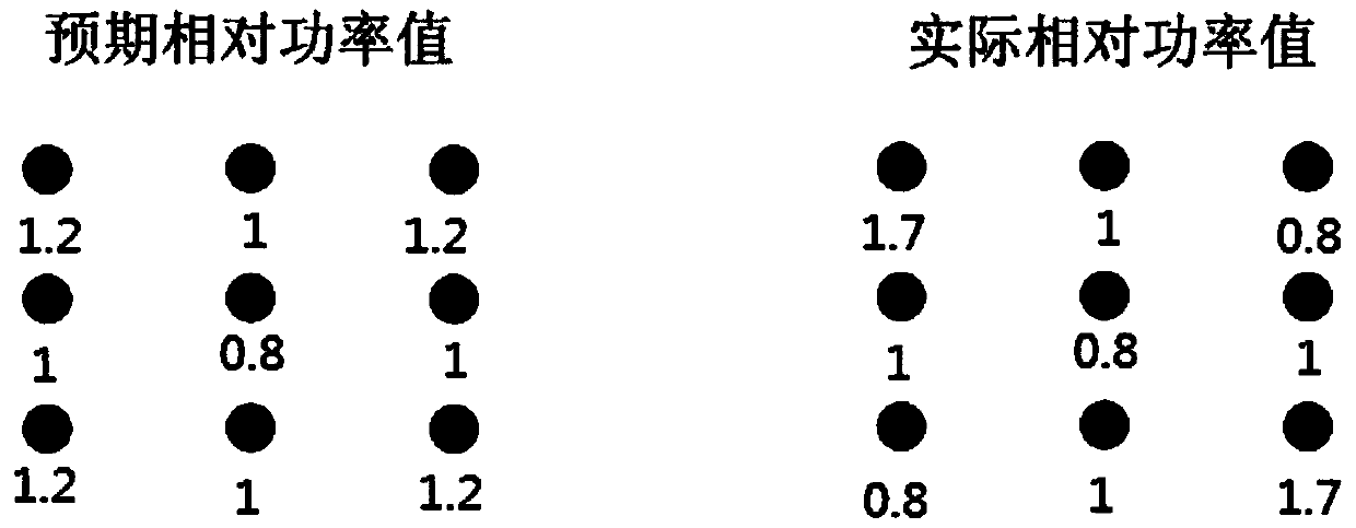
[0033] The structure adopted by this kind of diffractive optical element is usually a periodic arrangement of phase distribution Φ(i,j) (such as Image 6 As shown), such a structure makes when the manufacturing precision of the diffractive optical element is low, when the diffractive optical element splits the laser beam, the output sub-beam power is inconsistent with the expected power.

[0034] The diffractive optical element designed in the present invention includes phase distribution A and phase distribution B,...


PUM


Abstract

The invention relates to the technical field of optical elements, in particular to a diffractive optical element. In order to solve the problems of inconsistency between sub-beam power and expected power when a diffractive optical element that is high in manufacture error is used for beam splitting of light, the invention provides the diffractive optical element which comprises phase distribution A and phase distribution B. The phase distribution A conforms to 0 / cX<pi> binary distribution, where c is in a numerical range of 0.5-1.5. The phase distribution B compensates with the phase distribution A, that is, the sub beam power outputted when a laser passes through the phase distribution B compensates with the sub beam power outputted when a laser passes through the phase distribution A. The invention achieves compensation of the power between sub beams by means of combining the phase distribution A with the phase distribution B, so that the sub beam power is consistent with the expected power.

Description

technical field [0001] The invention relates to the technical field of designing optical elements, in particular to a diffractive optical element. Background technique [0002] Diffractive optical elements can be used in many fields, such as structured light for human-computer interaction, gesture recognition, robot vision, laser material processing (such as porous simultaneous processing, high-speed laser texturing), optical communication, optical image processing, microelectronics, Microscope, fiber coupling, etc. [0003] When the diffractive optical element is used to split the laser beam, it can convert a laser beam into multiple beams (usually called sub-beams). At this time, the diffractive optical element is usually called diffractive beam splitting element, array generator, splitting beam Beam grating, or simply grating, beam splitting element, etc. [0004] The U.S. Patent No. US2013120841 discloses an Optical pattern projector. The optical device in this patent ...

Claims


Application Information

Patent Timeline
Patent Type & Authority Patents(China)
IPC IPC(8): G02B27/09G02B27/42
CPCG02B27/0944G02B27/4244G02B27/4266
Inventor 刘劲松
Owner 无锡奥普顿光电子有限公司
Why Eureka
Try Eureka