Method for achieving rectifying tower splitting and heat coupling driven by heat transfer temperature difference

A technology of split thermal coupling and heat exchange temperature difference, which is applied in special data processing applications, instruments, electrical digital data processing, etc. It can solve the problems of inability to maximize energy saving of rectification towers and lack of thermal coupling design methods, and achieve pressure reduction requirements, energy consumption reduction, effect of reduced power requirements

Active Publication Date: 2016-04-20
ZHEJIANG UNIV
View PDF4 Cites 0 Cited by
  • Summary
  • Abstract
  • Description
  • Claims
  • Application Information

AI Technical Summary

Problems solved by technology

Although these methods excavate part of the energy-saving potential of the rectification tower through different internal thermal coupling designs of the rectification tower, the thermal coupling design method has no certain rules to follow, so it is impossible to maximize the energy saving of the rectification tower

Method used


Image

  • Method for achieving rectifying tower splitting and heat coupling driven by heat transfer temperature difference
  • Method for achieving rectifying tower splitting and heat coupling driven by heat transfer temperature difference
  • Method for achieving rectifying tower splitting and heat coupling driven by heat transfer temperature difference

Examples


Embodiment Construction

[0041] The present invention will be further described below in conjunction with embodiment.

[0042] Embodiments of the present invention and processes thereof are as follows:

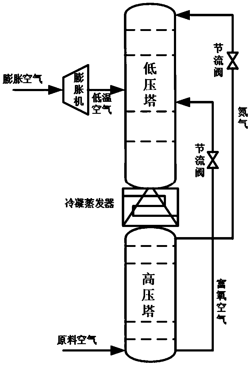
[0043] A large-scale air separation equipment rectification tower is used as the implementation object. The high-pressure tower contains 35 stages of trays, and the low-pressure tower contains 70 stages of trays.

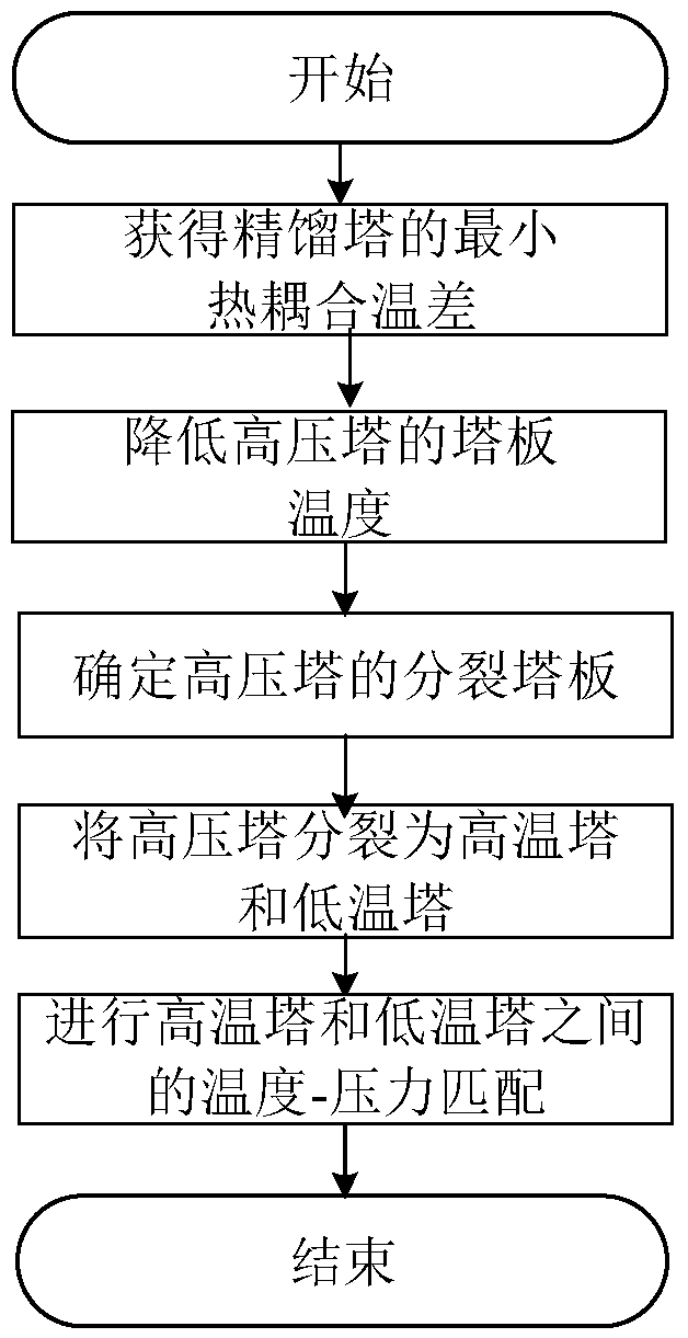
[0044] (1) According to the plate temperature data in the single-plate coupling mode of the rectification column, the minimum thermal coupling temperature difference ΔT between the high-pressure column and the low-pressure column of the rectification column is calculated to be 1.8K.

[0045] (2) According to the temperature data of the trays at all levels in the single-plate coupling mode of the rectification tower, take the number of trays at each level of the rectification tower as the abscissa, and the tray temperature as the ordinate, draw the tray temperature curve of the rectification...


PUM


Abstract

The invention discloses a method for achieving rectifying tower splitting and heat coupling driven by a heat transfer temperature difference. The method comprises the steps that tower plate temperature data of a rectifying tower in a single-plate coupling mode is collected; a temperature difference between coupling tower plates of a high-pressure tower and a low-pressure tower is obtained, and then a minimum heat coupling temperature difference of the rectifying tower is obtained; the coupling mode is changed into a tower top coupling mode, the high-pressure tower is arranged on the side portion of the low-pressure tower for heat coupling, and a splitting tower plate of the high-pressure tower is obtained by conducting step-by-step checking through a splitting tower plate selection mode from the tower top of the high-pressure tower; the high-pressure tower is split into a high-temperature tower body and a low-temperature tower body on the position of the splitting tower plate, the high-temperature tower body and the low-temperature tower body are arranged on the two sides of the low-pressure tower respectively and conduct coupling heat transfer with the low-pressure tower in a tower top coupling mode, and a throttle valve and a compressor are additionally arranged on mass transfer loops. According to the method for achieving rectifying tower splitting and heat coupling driven by the heat transfer temperature difference, a traditional coupling heat transfer mode of the rectifying tower is changed, the temperature of the tower bottom of the high-pressure tower can be decreased to the minimum by conducting coupling heat transfer on the split high-pressure tower and the tower top of the low-pressure tower, therefore, the working pressure of the tower bottom of the high-pressure tower is decreased to the minimum, the pressure requirement of the rectifying tower to raw material air is reduced, the requirement of a unit for the compressor power is reduced, and the energy consumption of the whole unit is reduced finally.

Description

technical field [0001] The invention relates to a thermal coupling method inside a rectification tower, in particular to a split thermal coupling method of a rectification tower driven by a heat exchange temperature difference. Background technique [0002] The rectification column is a key part of material separation in complex equipment such as large-scale air separation equipment and ethylene equipment, and its structure plays a decisive role in the energy-saving optimization of equipment. The rectification tower in the traditional large-scale air separation equipment is divided into a lower tower and an upper tower. The high-pressure feed air enters the rectification tower from the lower tower. The output of the upper tower is lower, so the upper tower is also called the low-pressure tower. The oxygen and nitrogen separation process inside the rectification tower is realized through coupled heat exchange between the high pressure tower and the low pressure tower of the ...

Claims


Application Information

Patent Timeline
Patent Type & Authority Applications(China)
IPC IPC(8): G06F17/50
CPCG06F30/20G06F2119/08G06F2119/18
Inventor 刘振宇郭云东彭翔谭建荣
Owner ZHEJIANG UNIV
Why Eureka
Try Eureka