Flexible device

A flexible device and flexible technology, applied in the field of flexible display, can solve problems such as changes in connection methods, and achieve the effect of reducing the possibility of cracking

Active Publication Date: 2016-04-20
BOE TECH GRP CO LTD
View PDF7 Cites 40 Cited by
  • Summary
  • Abstract
  • Description
  • Claims
  • Application Information

AI Technical Summary

Problems solved by technology

[0004] In view of this, the embodiment of the present invention provides a flexible device to solve the problem caused by changing the pos

Method used


Image

  • Flexible device
  • Flexible device
  • Flexible device

Examples


example 1

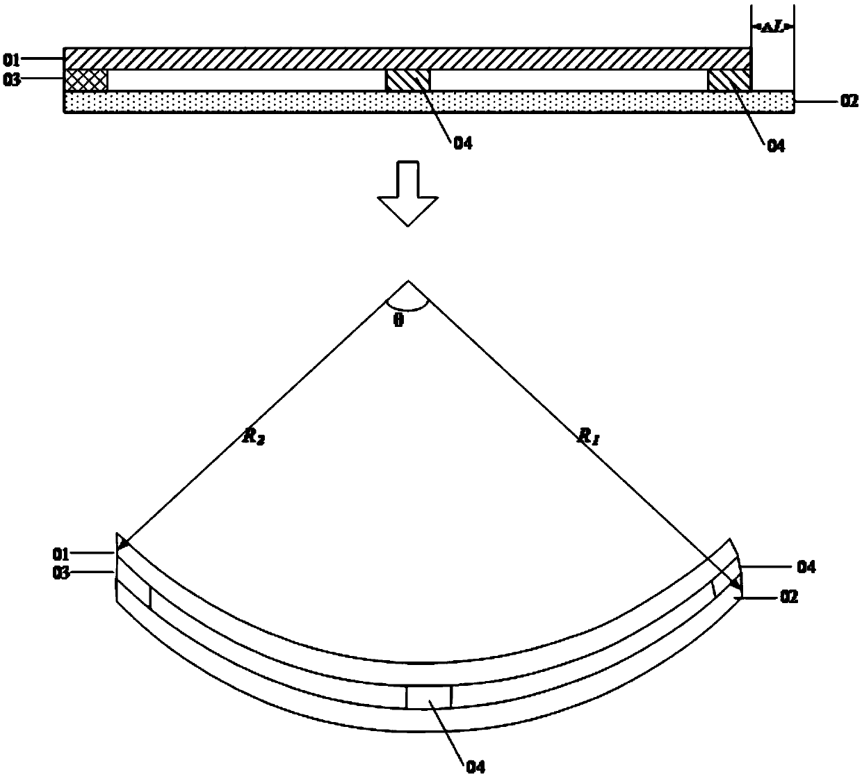
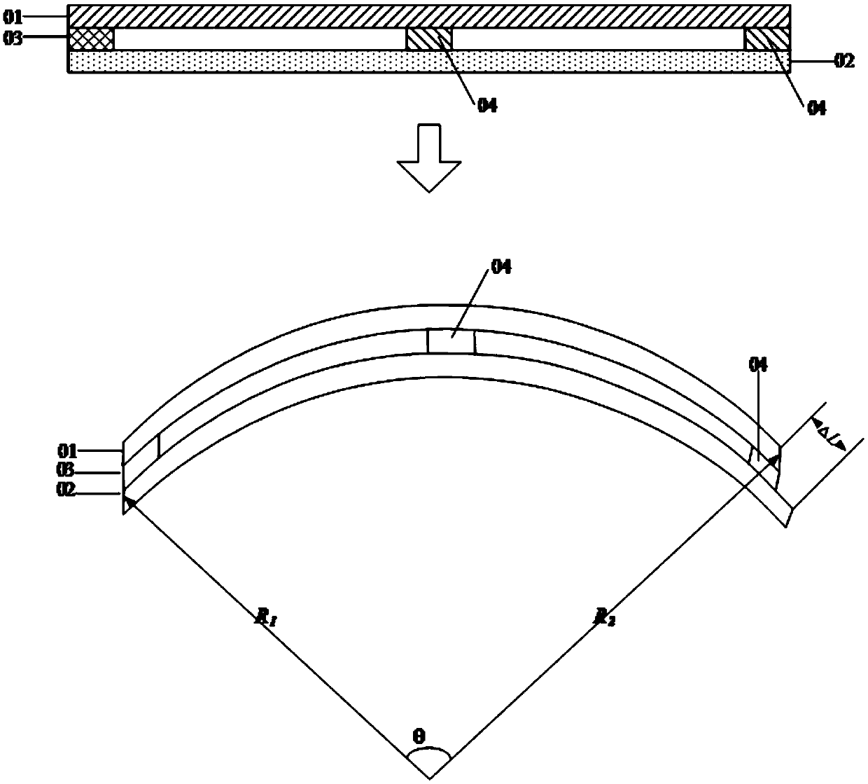
[0035] like Figure 1a and Figure 1b As shown, in this example, the glue structure 03 is fixed at one or more places between the flexible module 01 and the flexible support structure 02, that is, the glue structure 03 does not completely connect the surfaces of the flexible module 01 and the flexible support structure 02 They are fixed together so as to ensure that the flexible module 01 and the flexible support structure 02 can slide relative to each other when the flexible device is bent.

[0036] In practice, the location of the glue structure 03 in this example can be anywhere between the flexible module 01 and the flexible support structure 02, and the location of the glue structure 03 can be one place or multiple places. Preferably, if Figure 1a and Figure 1b As shown, the glue structure 03 is only fixed at one of the flexible modules 01 and the flexible support structure 02, for example, as Figure 1a and Figure 1b As shown, it is fixed at the edge position of the...

example 2

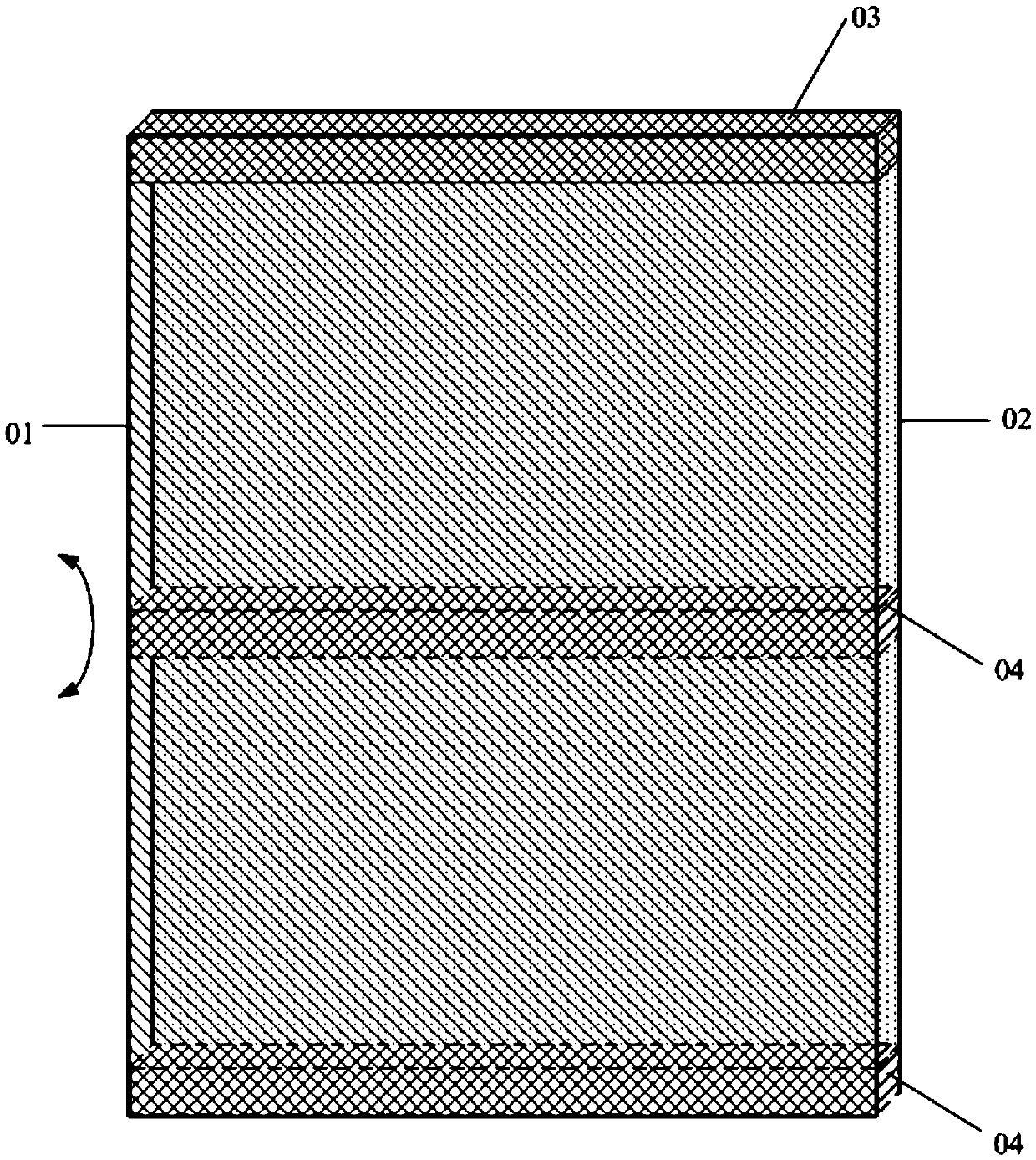
[0046] Such as Figure 4a with Figure 4b As shown, in this example, the glue structure 03 fills the entire area between the flexible module 01 and the flexible support structure 02; In order to enable the flexible module 01 and the flexible support structure 02 to slide relative to each other when the flexible device is bent, the adhesive structure 03 needs to be elastically deformed when the flexible device is bent. Therefore, the adhesive structure 03 should be selected with a very low elastic modulus. The adhesive material is used to ensure that it can undergo elastic deformation. Specifically, the elastic modulus of the adhesive structure is 80pa-500Mpa.

[0047] In the above two examples, there are two kinds of adhesives that can not only fix the flexible module 01 and the flexible support structure 02 to each other, but also enable the flexible module 01 and the flexible support structure 02 to slide relative to each other when the flexible device is bent. The impleme...


PUM


Abstract

The invention discloses a flexible device. The flexible device comprises a flexible module, a flexible support structure and a glue structure, wherein the flexible support structure is arranged opposite to the flexible module; the glue structure is used for fixing the flexible module and the flexible support structure together, and driving the flexible module and the flexible support structure to slide relatively when the flexible device is bent. Through the glue structure, the flexible module and the flexible support structure are fixed together, and a space for the flexible module and the flexible support structure to move relatively is formed between the flexible module and the flexible support structure when the flexible device is bent, so that the flexible module and the flexible support structure are independent of each other while the flexible module and the flexible support structure are integrated into a whole through the glue structure, and the position of a neutral layer in the flexible module is not changed. Thus, the probability of cracking between membrane layers in the flexible module is lowered in a bending process. Moreover, under the condition that the flexible module is constant in thickness, the flexible device is bent to a smaller bending radius.

Description

technical field [0001] The present invention relates to the technical field of flexible display, in particular to a flexible device. Background technique [0002] At present, flexible modules that can be bent or folded have been developed. The flexible module is a multi-layer structure. For example, a flexible display panel designed based on an electroluminescent structure generally includes a laminated back film, a pixel control circuit, Electroluminescent pixel components, water and oxygen barrier layer (BF), circular polarizer (C-POL), touch component (Touch), and protective cover (HC) and other film layers, usually the overall thickness of the module is 200- 600 μm. [0003] When the flexible module and the supporting and fixing mechanical structure are integrated into a complete machine, the mechanical structure and the flexible module are all attached and fixed together, which is equivalent to indirectly increasing the thickness of the overall flexible module and chan...

Claims


Application Information

Patent Timeline
IPC IPC(8): G09F9/00G09F9/30
CPCG09F9/00G09F9/301B32B3/08B32B7/14B32B2250/02B32B2307/50B32B2457/20B32B7/05G06F1/1652B32B2255/26B32B2307/412B32B2307/51G06F1/16G09F9/30H05K5/0017
Inventor 刘陆周伟峰
Owner BOE TECH GRP CO LTD
Why Eureka
Try Eureka