Direct-current change-over switch

A DC conversion and switching technology, which is applied in the direction of electric switches, high-voltage/high-current switches, high-voltage air circuit breakers, etc., can solve the problems that the current capacity of DC conversion switches cannot meet the requirements of DC field projects, and achieve improved power supply reliability and durability Good pollution performance and improved flow capacity

Inactive Publication Date: 2016-04-20
PINGGAO GRP +3
View PDF4 Cites 3 Cited by
  • Summary
  • Abstract
  • Description
  • Claims
  • Application Information

AI Technical Summary

Problems solved by technology

[0003] Among the DC transfer switches developed at home and abroad, the rated current capacity is generally not greater than 7000A. With the increasing requirements of the UHV project on the transfer switch, the current capacity of the existing DC transfer switch is difficult to meet the requirements of the DC field. The needs of the project are very necessary for the research and development of the transfer switch with large flow capacity

Method used


Image

  • Direct-current change-over switch
  • Direct-current change-over switch
  • Direct-current change-over switch

Examples


Embodiment Construction

[0021] Embodiments of the present invention will be further described below in conjunction with the accompanying drawings.

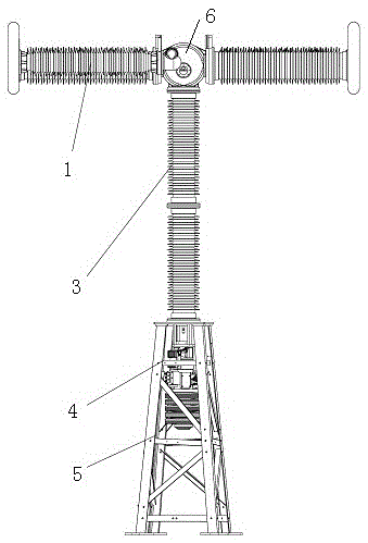
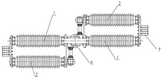
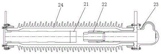
[0022] A specific embodiment of the DC conversion switch of the present invention, such as Figure 1 to Figure 3 As shown, the DC conversion switch includes a bracket 5 and a column 3 erected on the bracket 5. A drive mechanism 4 located below the column 3 is fixed in the bracket 5. An arc extinguishing assembly is fixed on the upper end of the column 3. The arc extinguishing assembly includes a main extinguishing The arc chamber 1 and the split arc chamber 2 connected in parallel at both ends of the main arc chamber 1 . A triple box 6 is provided between the upper end of the pillar 3 and the main interrupter 1. The triple box 6 includes a driving crank arm, and the driving crank arm includes an input arm and an output arm. The driving mechanism 4 is connected to the input arm through a transmission rod, and the transmission rod The movable assembly is ...


PUM


Abstract

The invention relates to a direct-current change-over switch. The direct-current change-over switch comprises a supporting post and a main arc extinguish chamber which is fixed on the supporting post; a shunt arc extinguish chamber is arranged in parallel with the main arc extinguish chamber. According to the direct-current change-over switch, the shunt arc extinguish chamber is arranged in parallel with the main arc extinguish chamber, the original arc extinguish chamber structure is unnecessary to change, and when a brake is closed, the main arc extinguish chamber and the shunt arc extinguish chamber share making current and rated current commonly, so that the overall through-current capability of the direct-current change-over switch is improved; the problem that the bearable through-current capability of the existing direct-current change-over switch is low is solved; the requirement on a project in a direct current field can be met.

Description

technical field [0001] The invention relates to a direct current conversion switch. Background technique [0002] In the DC field equipment, the function of the DC transfer switch is to convert the DC operating current in the HVDC transmission system from one operating loop to another operating loop, which can ensure that the transmission of DC power is not interrupted during the conversion process. [0003] Among the DC transfer switches developed at home and abroad, the rated current capacity is generally not greater than 7000A. With the increasing requirements of the UHV project on the transfer switch, the current capacity of the existing DC transfer switch is difficult to meet the requirements of the DC field. The needs of the project are very necessary for the research and development of the transfer switch with large flow capacity. Contents of the invention [0004] The purpose of the present invention is to provide a DC transfer switch with improved current flow ca...

Claims


Application Information

Patent Timeline
Patent Type & Authority Applications(China)
IPC IPC(8): H01H33/12
CPCH01H33/123
Inventor 门博仝永刚孙珂珂马志华程铁汉胡延涛熊萍萍朱继斌
Owner PINGGAO GRP
Why Eureka
Try Eureka