Multilevel spare power automatic switching system, priority cooperation method, and construction method

A self-initiated and prioritized technology, applied in information technology support systems, power network operating system integration, sustainable buildings, etc., to achieve the effect of easy implementation, less equipment, and easy implementation

Inactive Publication Date: 2016-04-20
NR ELECTRIC CO LTD +1
View PDF6 Cites 15 Cited by
  • Summary
  • Abstract
  • Description
  • Claims
  • Application Information

AI Technical Summary

Problems solved by technology

[0007] The purpose of the present invention is to provide a multi-level backup and automatic switching system, which can solve the problems of multiple sets of backup and automatic switching in substations, in view of the problems in the priority coordination of traditional backup and automatic switching in regional power grids and the diffic

Method used


Image

  • Multilevel spare power automatic switching system, priority cooperation method, and construction method
  • Multilevel spare power automatic switching system, priority cooperation method, and construction method
  • Multilevel spare power automatic switching system, priority cooperation method, and construction method

Examples


Embodiment Construction

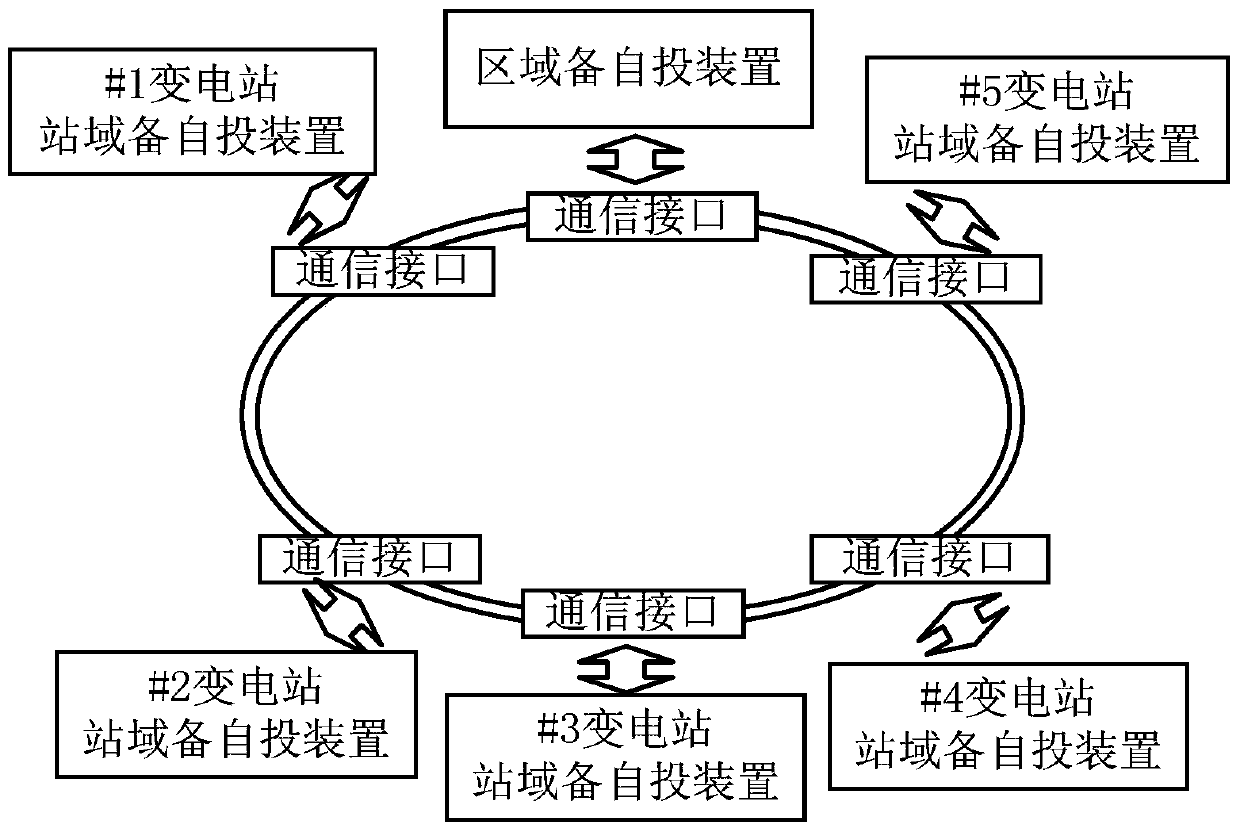
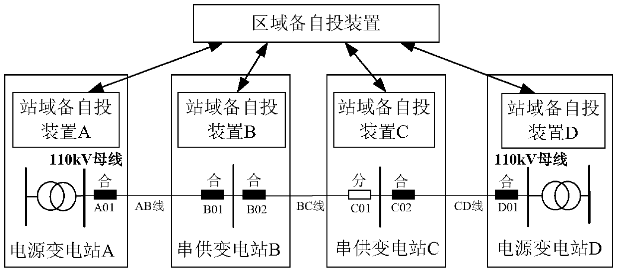
[0023] The technical solutions of the present invention will be described in detail below in conjunction with the accompanying drawings.

[0024] The implementation of multi-level equipment self-injection system of the present invention has following steps:

[0025] The first step: implement station domain standby self-commissioning in each substation of the regional power grid:

[0026] A hardware configuration for self-switching of station domain backup is as follows: figure 1 As shown, the structure of multiple boards is adopted: A is the man-machine interface board, which realizes the function processing of the man-machine interface and background communication; B / C / D / E are 4 CPU boards, which realize the logic of automatic switching of each set of equipment Function; H is the inter-station communication board, used as an interface for communicating with other substations; J is a digital interface board, used to receive digital analog and switch input; K is an input board...


PUM


Abstract

The invention discloses a multilevel spare power automatic switching system, which is suitable for a regional power grid adopting one or a plurality of 220kV transformer station/s as power supply and a plurality of 110kV transformer stations. The multilevel spare power automatic switching system is constituted by a plurality of substation area spare power automatic switching devices and a regional spare power automatic switching device. The substation area spare power automatic switching devices are disposed on the transformer stations in the regional power grid, and are provided with the spare power automatic switching functions of various voltage levels of the transformer stations. The regional spare power automatic switching device is disposed on any transformer station in the regional power grid, and can be used to acquire the information of the transformer stations from the substation area spare power automatic switching devices via the real-time communication network, and the regional spare power automatic switching function can be realized. The multilevel spare power automatic switching system comprises 220kV power supply transformation spare power automatic switching devices, a regional spare power automatic switching, 110 kV transformer station high voltage side spare power automatic switching devices, and 110kV transformer station middle-lower voltage side spare power automatic switching devices, which are provided with the multilevel spare power automatic switching function having the differentiated priorities. The invention also discloses a method for realizing priority cooperation of the multilevel spare power automatic switching devices by the logical command.

Description

technical field [0001] The invention relates to an automatic switching system and method for power transmission and distribution in a power system, in particular to a backup power automatic switching system, a priority coordination method and a construction method. Background technique [0002] In recent years, backup power self-switching technology has been widely used in 220kV and below power grids, and has played an important role in maintaining grid stability and improving power supply reliability. [0003] Traditional standby automatic switching devices are generally configured according to voltage levels. In a substation, multiple sets of standby automatic switching devices will be configured according to different voltage levels. Generally, there is no exchange of information between the standby automatic switching devices. The automatic switch has a priority coordination relationship. The standby automatic switch on the high-voltage side has priority over the standby...

Claims


Application Information

Patent Timeline
IPC IPC(8): H02J9/06H02J13/00
CPCY04S20/12Y02B90/20Y04S20/20Y02B70/30
Inventor 文屹董凯达刘孝旭金震廖清阳张春合徐平余群兵陈飞建严伟王荣李学洪杨欣胡绍勇江开伦冷贵峰杨光祝远来樊国盛
Owner NR ELECTRIC CO LTD
Why Eureka
Try Eureka