
Induction motor

A technology for induction motors and rotors, which is applied in the direction of electric components, electrical components, electromechanical devices, etc. It can solve the problems of small diameter of cast copper rotors, difficult two-way chute, high efficiency requirements, etc., and achieve good running effect, low vibration and noise, Easy to install and fix

Inactive Publication Date: 2016-04-20
CHINA NAT OFFSHORE OIL CORP +1
View PDF6 Cites 4 Cited by
  • Summary
  • Abstract
  • Description
  • Claims
  • Application Information

AI Technical Summary

Problems solved by technology

With the cast aluminum rotor, it is easy to realize that the rotor core adopts a one-way chute or a two-way chute, but this method is only suitable for small induction motors
For medium and large induction motors, especially marine induction propulsion motors, the efficiency requirements are high, and it is impossible to use cast aluminum rotors, while cast copper rotors are complex in process and require high equipment, and the diameter of cast copper rotors is generally small, which is not suitable for large and medium-sized induction motors. electric motor
Medium and large induction motors generally use guide bar rotors. At the same time, considering the heat dissipation of the motor, radial ventilation grooves need to be installed on the stator core and rotor core. Large and medium-sized induction motors use chute to meet the requirements of low vibration and low noise

Method used


Image

  • Induction motor
  • Induction motor
  • Induction motor

Examples


Embodiment Construction

[0022] In order to make the purpose, technical solutions and advantages of this document clearer, the embodiments of this document will be described in detail below in conjunction with the accompanying drawings. It should be noted that, in the case of no conflict, the embodiments in the present application and the features in the embodiments can be combined arbitrarily with each other.

[0023] In the following description, a lot of specific details are set forth in order to fully understand this article, but this article can also be implemented in other ways than described here, therefore, the protection scope of this article is not limited by the specific embodiments disclosed below .

[0024] The induction motors of some embodiments herein are described below with reference to the accompanying drawings.

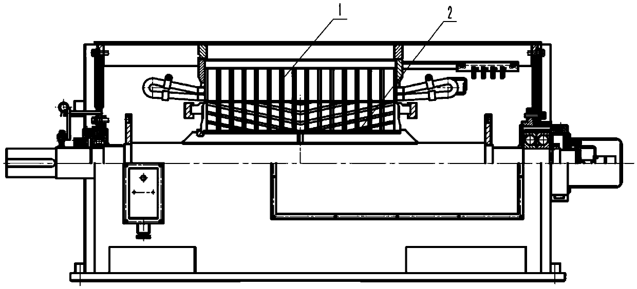
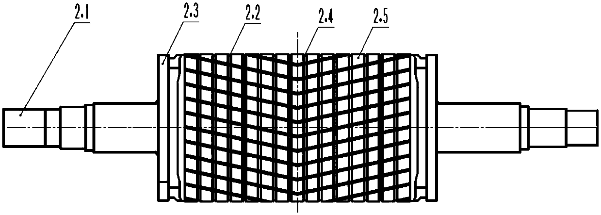
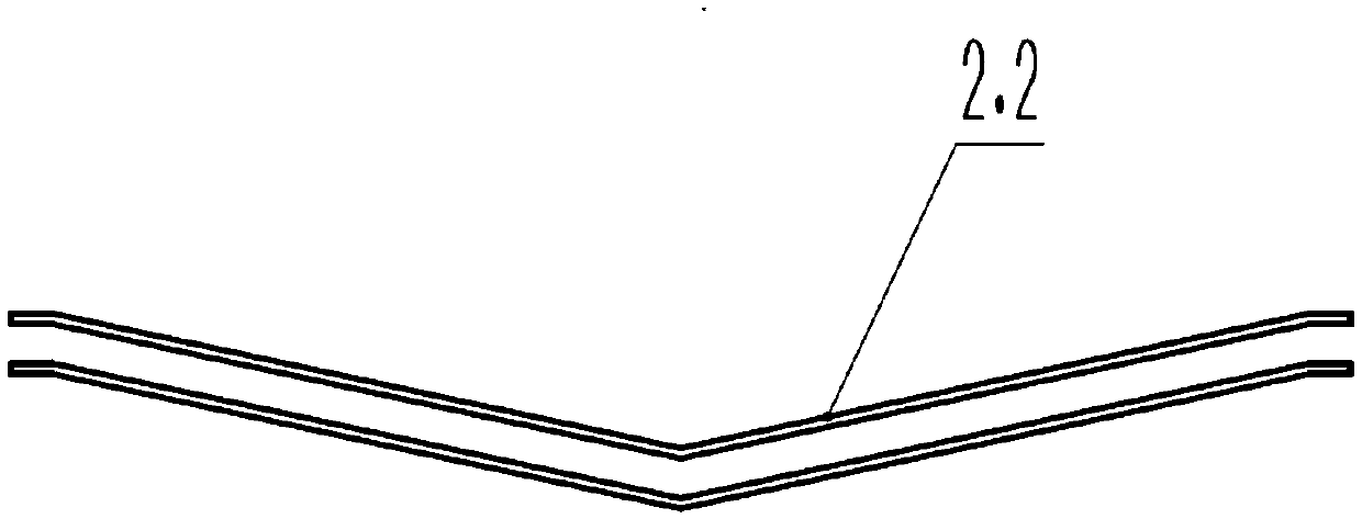
[0025] This paper provides induction motors such as Figure 1 to Figure 3 As shown, including the rotor 2 and the stator 1, the rotor 2 includes: a rotating shaft 2.1; t...


PUM


Abstract

The invention discloses an induction motor which comprises a rotor and a stator. The rotor comprises a rotating shaft, two end rings, multiple rotor ventilating groove plates, multiple rotor iron cores, multiple V-shaped guide bars mutually independent, wherein the two end rings are installed on the rotating shaft in a spaced mode, the rotor ventilating groove plates and the rotor iron cores are located between two end rings, installed on the rotating shaft and arranged alternately, the V-shaped guide bars are sequentially installed on the rotor iron cores in the circumferential direction, the two ends of any guide bar are connected with the two end rings in a one-to-one corresponding mode, a plurality of V-shaped installing grooves are uniformly formed in the rotor iron cores in the axial direction, and the guide bars are installed in the multiple installing grooves in a one-to-one corresponding mode. According to the induction motor, the V-shaped installing grooves on the rotor iron cores are symmetrical inclined grooves, radial force can be reduced, amplitude and noise are reduced, working environment is improved, it is ensured that electromagnetic vibration of the motor in the forward and reverse operation process is restrained to the maximum degree, and the operation effect is better.

Description

technical field [0001] This paper relates to, but is not limited to, power equipment technology, especially an induction motor. Background technique [0002] In the prior art, in order to reduce the electromagnetic vibration and noise of the induction motor, the stator iron core adopts a one-way inclined slot with one tooth pitch, or the rotor iron core adopts an inclined slot to reduce tooth harmonics. However, in the actual implementation process, it was found that when the induction motor power exceeds 500kW, and the induction motor requires forward and reverse operation, the stator one-way inclined slot is used, and the effect of reducing tooth harmonics is not obvious. An effective measure to reduce tooth harmonics is to use a two-way chute. With the cast aluminum rotor, it is easy to realize that the rotor iron core adopts a one-way chute or a two-way chute, but this method is only suitable for small induction motors. For medium and large induction motors, especially...

Claims


Application Information

Patent Timeline
Patent Type & Authority Applications(China)
IPC IPC(8): H02K1/26
CPCH02K1/265
Inventor 蔡钿梁天山池波陈诺
Owner CHINA NAT OFFSHORE OIL CORP
Learn More