A piston protector

A protector, piston technology, applied in electrical components, electromechanical devices, structural connections, etc., can solve the problems of O-ring damage, unreasonable structural design, loss of protective effect of the protector, etc., and achieve the effect of preventing damage.

Active Publication Date: 2018-05-04
DONGFANG ELECTRIC MACHINERY
View PDF9 Cites 0 Cited by
  • Summary
  • Abstract
  • Description
  • Claims
  • Application Information

AI Technical Summary

Problems solved by technology

[0006] The automatic oil-free submersible motor protector disclosed in this patent document has an unreasonable structural design, especially the spring connecting the piston. After long-term use, the elastic force decreases, and it is difficult for the piston to pass through the O-ring to seal the annular oil under the action of the spring. The external medium is easy to directly contact the O-ring, causing the O-ring to be damaged, making it difficult to achieve self-balancing of the internal and external pressure difference, and then making the protector lose its protective effect and affecting the normal operation of the motor

Method used


Image

  • A piston protector
  • A piston protector
  • A piston protector

Examples


Embodiment 1

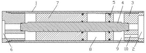
[0042] See figure 1 , A piston protector, comprising a housing 1 and a support 3 connected to the internal medium cavity 2, the support 3 is fixed on the housing 1, and also includes a piston rod 4 fixed on the support 3, the piston rod 4 is located In the housing 1, a first piston 5 and a second piston 7 communicating with an external medium cavity 6 are connected between the piston rod 4 and the housing 1 through a sealing ring. The first piston 5, the second piston 7, The housing 1 and the piston rod 4 enclose a transition cavity 8. The first piston 5, the housing 1, the piston rod 4 and the support 3 enclose a thin oil chamber 9, and the support 3 is provided with an oil through hole 10 , The oil through hole 10 communicates with the thin oil cavity 9 and the internal medium cavity 2 respectively.

[0043] This embodiment is the most basic implementation. The piston rod is located in the housing. The first piston and the second piston communicating with the external medium ca...

Embodiment 2

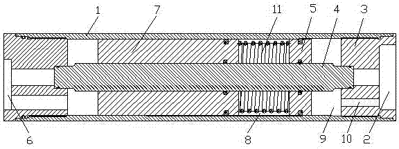
[0045] See figure 2 , A piston protector, comprising a housing 1 and a support 3 connected to the internal medium cavity 2, the support 3 is fixed on the housing 1, and also includes a piston rod 4 fixed on the support 3, the piston rod 4 is located In the housing 1, a first piston 5 and a second piston 7 communicating with an external medium cavity 6 are connected between the piston rod 4 and the housing 1 through a sealing ring. The first piston 5, the second piston 7, The housing 1 and the piston rod 4 enclose a transition cavity 8. The first piston 5, the housing 1, the piston rod 4 and the support 3 enclose a thin oil chamber 9, and the support 3 is provided with an oil through hole 10 , The oil through hole 10 communicates with the thin oil cavity 9 and the internal medium cavity 2 respectively.

[0046] An elastic element 11 is installed in the transition cavity 8.

[0047] The elastic element 11 is a spring, one end of the spring is connected to the first piston 5, and th...

Embodiment 3

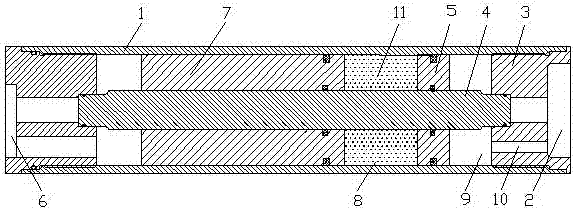
[0050] See image 3 , A piston protector, comprising a housing 1 and a support 3 connected to the internal medium cavity 2, the support 3 is fixed on the housing 1, and also includes a piston rod 4 fixed on the support 3, the piston rod 4 is located In the housing 1, a first piston 5 and a second piston 7 communicating with an external medium cavity 6 are connected between the piston rod 4 and the housing 1 through a sealing ring. The first piston 5, the second piston 7, The housing 1 and the piston rod 4 enclose a transition cavity 8. The first piston 5, the housing 1, the piston rod 4 and the support 3 enclose a thin oil chamber 9, and the support 3 is provided with an oil through hole 10 , The oil through hole 10 communicates with the thin oil cavity 9 and the internal medium cavity 2 respectively.

[0051] An elastic element 11 is installed in the transition cavity 8.

[0052] The elastic element 11 is gas, and the gas fills the transition cavity 8.

[0053] This embodiment is ...


PUM


Abstract

The invention discloses a piston type protector and belongs to the technical field of underground drilling tool motors. The piston type protector comprises a shell and a support for connecting an inner medium cavity, wherein the support is fixed on the shell; the piston type protector is characterized by further comprising a piston rod fixed on the support; the piston rod is located in the shell; a first piston and a second piston communicated with an outer medium cavity are connected between the piston rod and the shell through sealing rings; a transitional cavity is defined by the first piston, the second piston, the shell and the piston rod; a thin oil cavity is defined by the first piston, the shell, the piston rod and the support; an oil through hole is formed in the support; the oil through hole is communicated with the thin oil cavity and the inner medium cavity respectively. By adopting a double-piston structure, self-balance of inner and outer pressure difference is realized; pressure pulse in a whole working process of the protector is effectively reduced and the operational reliability is improved, so that the piston type protector can guarantee that the motor is normally and stably operated for a long time.

Description

Technical field [0001] The invention relates to the technical field of downhole drilling tool motors, in particular to a piston type protector suitable for downhole drilling tool motors. Background technique [0002] The motor is in a high temperature and high pressure environment when working underground. The high temperature causes the internal medium of the motor to expand, and the high voltage environment outside the motor also causes a large pressure difference between the inside and outside of the motor. The expansion of the internal medium and the huge pressure difference between the inside and outside Existence makes the motor unable to achieve sealing, and at the same time it will cause huge damage to the structural components of the motor. Therefore, motors working in underground mines are often equipped with protectors. The main function of the protectors is to balance the pressure between the inside of the motor and the outside of the motor, so that the pressure diffe...

Claims


Application Information

Patent Timeline
Patent Type & Authority Patents(China)
IPC IPC(8): H02K11/20
CPCH02K2213/09
Inventor 林坤孙立宾李少斌李彬
Owner DONGFANG ELECTRIC MACHINERY
Why Eureka
Try Eureka