3D MIMO communication method and apparatus
A reference signal and A-CSI technology, applied in channel estimation, signaling allocation, signaling as a feature, etc., can solve the problem of unacceptable air interface overhead
- Summary
- Abstract
- Description
- Claims
- Application Information
AI Technical Summary
Problems solved by technology
Method used
Image
Examples
Embodiment 1
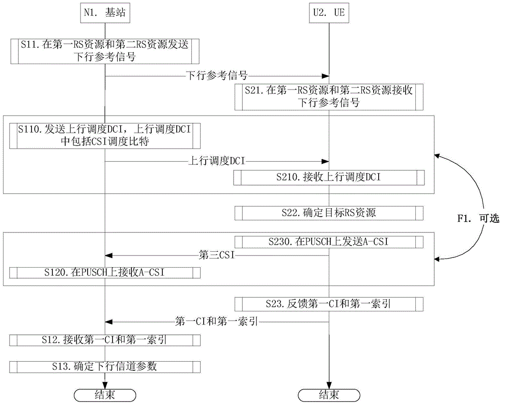
[0100] Embodiment 1 is a flowchart of CSI feedback, as attached figure 2 Shown. Attached figure 2 Among them, one cell maintained by the base station N1 is the serving cell of UEU2. Attached figure 2 , The steps in the box identified by F1 are optional steps.
[0101] For the base station N1, in step S11, the downlink reference signal is sent in the first RS resource and the second RS resource; in step S12, the first CI and the first index are received; in step S13, the downlink channel parameters are determined.
[0102] For UEU2, in step S21, the downlink reference signal is received in the first RS resource and the second RS resource; in step S22, the target RS resource is determined, and the target RS resource is the first RS resource or the second RS resource; In step S23, the first CI and the first index are fed back.
[0103] In Embodiment 1, the first RS resource includes N1 RS ports, and the second RS resource includes N2 RS ports, where N1 is a positive integer greater...
Embodiment 2
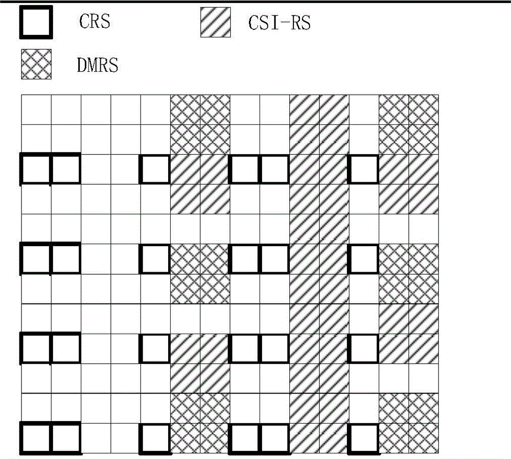
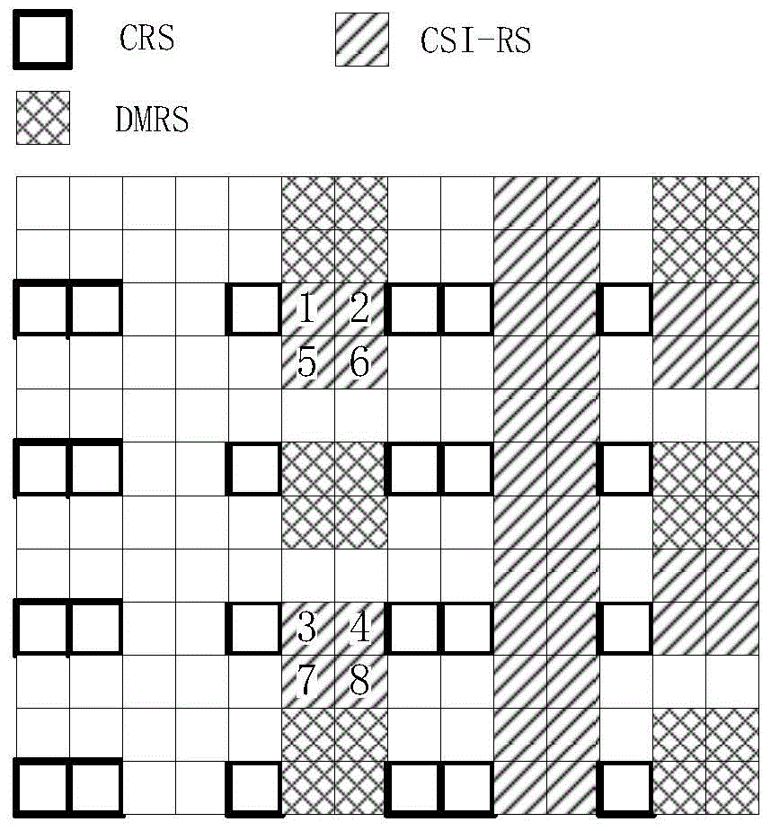
[0110] Embodiment 2 is the pattern of the first RS resource and the second RS resource in the PRBP, as shown in the appendix image 3 As shown, the RE identified by the number x corresponds to the RS port x-two REs on the same subcarrier adjacent in the time domain adopt OCC (Orthogonal Covering Code). Attached image 3 In, the first RS resource and the second RS resource occupy the CSI-RS resource in LTE, as shown in the appendix image 3 Shown in the square marked by the slash.
[0111] In Embodiment 2, the first RS resource includes RS ports {1, 2, 3, 4}, and the second RS resource includes RS ports {5, 6, 7, 8}. The first RS resource and the second RS resource respectively occupy the time, frequency, and code domain resources of a group of 4 CSI-RS ports in LTE.
Embodiment 3
[0113] Embodiment 3 is the mapping diagram from the 4X4 cross-polarized antenna array configured on the base station side to the RS port, as attached Figure 4 Shown. Attached Figure 4 In, a small square represents a physical antenna, and the number in it represents the RS port index corresponding to the physical antenna.
[0114] As attached Figure 4 As shown, the four transmit antennas in the first polarization direction of the same row are mapped to the same RS port by precoding (that is, the four transmit antennas respectively transmit the signals of the RS sequence of the same RS port after phase rotation, and the UE A virtual antenna is formed on the side). Similarly, the four transmit antennas in the second polarization direction in the same column are mapped to the same RS port in a precoding manner.
[0115] In Embodiment 3, the base station first sends downlink reference signals to the UE in the first RS resource and the second RS resource; the UE then determines the t...
PUM
 Abstract
Description
Claims
Application Information
 - R&D
- Intellectual Property
- Life Sciences
- Materials
- Tech Scout
- Unparalleled Data Quality
- Higher Quality Content
- 60% Fewer Hallucinations
Browse by: Latest US Patents, China's latest patents, Technical Efficacy Thesaurus, Application Domain, Technology Topic, Popular Technical Reports.
© 2025 PatSnap. All rights reserved.Legal|Privacy policy|Modern Slavery Act Transparency Statement|Sitemap|About US| Contact US: help@patsnap.com


