
Steam conveying pipeline device for ironing of cloth spreading machine

A technology for conveying pipelines and spreading machines, applied in textiles and papermaking, fabric surface trimming, spraying/jetting textile material treatment, etc., to achieve outstanding effects, simple structure, and convenient installation

Active Publication Date: 2016-04-27
BULLMER ELECTROMECHANICAL TECH
View PDF6 Cites 1 Cited by
  • Summary
  • Abstract
  • Description
  • Claims
  • Application Information

AI Technical Summary

Problems solved by technology

[0003] The purpose of the present invention is to provide a steam delivery pipeline device for ironing of a spreading machine which can solve the problem of steam delivery and ensure the stability of the steam pressure

Method used


Image

  • Steam conveying pipeline device for ironing of cloth spreading machine

Examples


Embodiment Construction

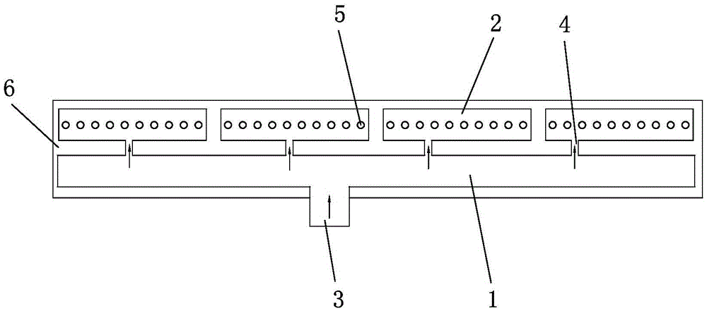
[0015] The present invention will be further described below with specific embodiment, see figure 1 :

[0016] A steam conveying pipeline device for ironing of a spreader, comprising a main steam pipeline 1 and several branch pipelines 2, the main steam pipeline 1 is provided with a main steam inlet 3 and connecting pipes 4 with several branch pipelines . Each branch pipe 2 communicates with the main steam pipe 1 through a branch pipe connecting pipe 4 , and each branch pipe 2 is provided with a nozzle connection hole 5 . The steam is input from the main steam inlet 3 and sent into the branch pipe 2 through the branch pipe connecting pipe 4 . The nozzle connecting holes 5 on each branch pipe 2 are provided in a row.

[0017] In the above technical solution, the main steam pipeline 1 and several branch pipelines 2 are arranged in the cavity surrounded by the heat insulation board 6 . The setting of the heat insulation board 6 can reduce the heat dissipation of the main stea...


PUM


Abstract

The invention belongs to the technical field of cloth spreading machines and particularly relates to a steam conveying pipeline device for ironing of a cloth spreading machine. The steam conveying pipeline device comprises a main steam pipeline and a plurality of branch pipelines, wherein a main steam inlet and a plurality of branch pipeline connection pipes are arranged on the main steam pipeline, each branch pipeline is communicated with the main steam pipeline through the corresponding branch pipeline connection pipe, and a spray nozzle connection hole is formed in each branch pipeline. The steam conveying pipeline device mainly solves the problem of steam conveying and guarantees stability of steam pressure and smooth ironing.

Description

Technical field: [0001] The invention belongs to the technical field of cloth spreading machines, in particular to a steam conveying pipeline device for ironing of cloth spreading machines. Background technique: [0002] In the clothing industry, cloth spreading is required before cutting, that is, the cloth is laid out in a certain size and stacked in multiple layers. Previously, clothing companies used manual spreading of fabrics on the spreading table for spreading. Due to the low efficiency of manual spreading, spreading machines have appeared on the market, which has greatly improved the spreading efficiency. At present, the fabrics in garment factories do not have special wake-up and spreading devices before spreading, so they often need to spend a long time (generally one day and one night) to let the elastic fabric return to its natural state and ensure better spreading. The effect is time-consuming and affects the production process. Therefore, it is necessary to...

Claims


Application Information

Patent Timeline
Patent Type & Authority Applications(China)
IPC IPC(8): D06C15/00D06B1/02
CPCD06B1/02D06C15/00
Inventor 娄正宇姚金领邵剑
Owner BULLMER ELECTROMECHANICAL TECH
Learn More