Quasi-free piston internal combustion engine

An internal combustion engine and piston technology, which is applied in the field of quasi-free piston internal combustion engine, can solve the problems of large inertial force, large mass of reciprocating moving parts, and strong vibration of the unit, and achieve the effect of reducing vibration

Inactive Publication Date: 2011-05-04
潍坊威度电子科技有限公司
View PDF4 Cites 7 Cited by
  • Summary
  • Abstract
  • Description
  • Claims
  • Application Information

AI Technical Summary

Problems solved by technology

[0005] 1. The mover of the linear generator makes a reciprocating linear motion together with the power rod. The mass of the reciprocating part is too large, which generates a large inertial force during operation, resulting in strong vibration of the unit;
[0006] 2. Using the air cushion to restrict the stroke of the piston, the position of the upper and lower dead centers of the piston cannot be precisely controlled, and the compression ratio is not fixed

Method used


Image

  • Quasi-free piston internal combustion engine
  • Quasi-free piston internal combustion engine
  • Quasi-free piston internal combustion engine

Examples


Embodiment 1

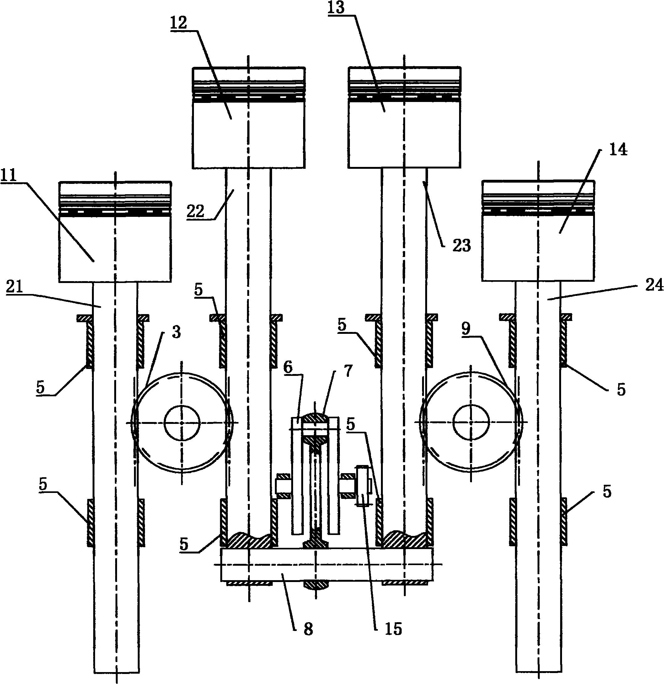
[0023] Such as figure 1 Shown, a kind of quasi-free-piston internal combustion engine of four-cylinder four-stroke, it comprises the first piston 11, the second piston 12, the third piston 13 and the fourth piston 14 that are arranged in parallel from left to right, and described four pistons all Installed in their respective cylinders. The four pistons are sequentially fixedly connected with a first power rod 21, a second power rod 22, a third power rod 23 and a fourth power rod 24, and the four power rods are respectively restrained in the linear bearing 5, and the linear The bearing 5 is arranged on the cylinder block, and the linear bearing 5 acts as a guide. For this purpose, other structures can also be used to linearly constrain the four power rods on the cylinder block.

[0024] A linkage shaft 8 is installed between the second power rod 22 and the third power rod 23, gear teeth are arranged on the surfaces adjacent to the first power rod 21 and the second power rod 2...

Embodiment 2

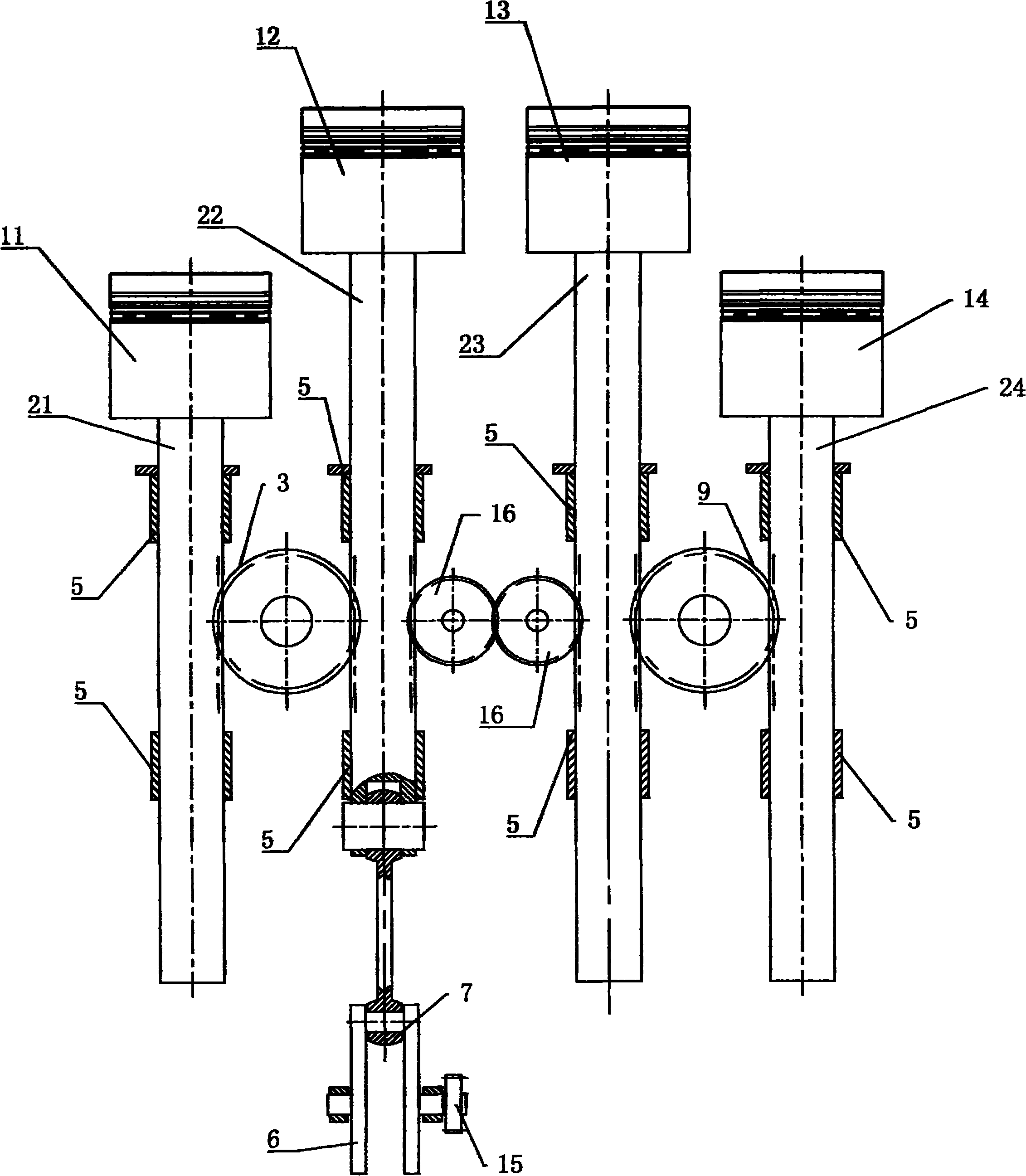
[0029] figure 2 What is shown is also a quasi-free piston internal combustion engine with four cylinders and four strokes. Its structure is basically the same as that of Embodiment 1. Linkage device, the same-direction linkage device includes a pair of interlocking gears 16 that are engaged with each other and rotatably mounted on the cylinder block of the internal combustion engine, and the opposite sides of the two adjacent power rods that move in the same direction are respectively provided with wheels Teeth, said gear teeth respectively mesh with a corresponding linkage gear. At this time, one end of the connecting rod 7 is hinged to a connecting rod journal of the crankshaft 6 , and the other end is hinged to the end of one of the power rods, such as the second power rod 22 .

Embodiment 3

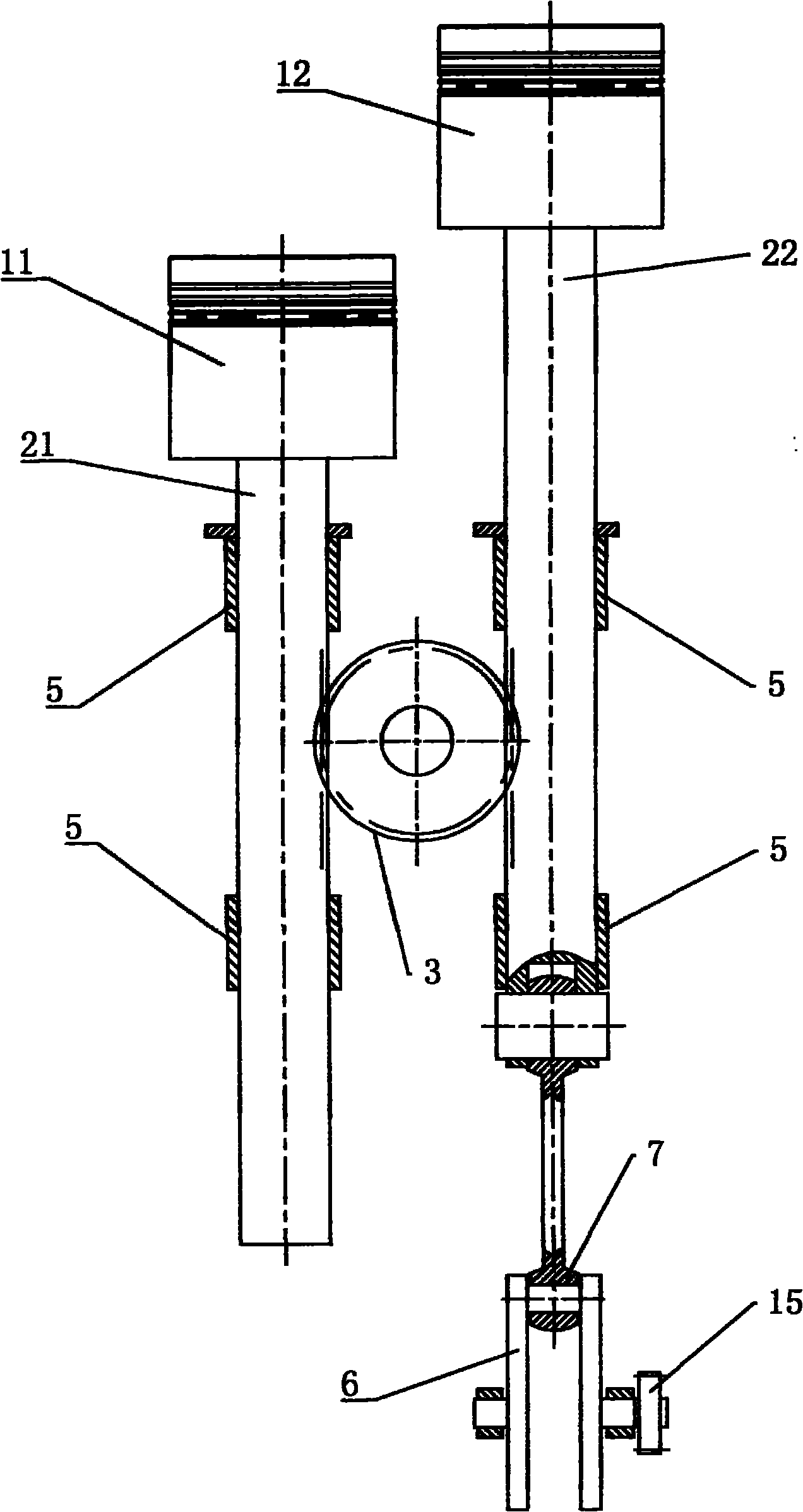
[0031] Such as image 3 As shown, a quasi-free piston internal combustion engine with two cylinders and two strokes, its structure is actually a simplified version of embodiment 2, and only two pistons moving in opposite directions and the necessary structure for ensuring operation thereof have been selected.


PUM


Abstract

The invention discloses a quasi-free piston internal combustion engine. In the internal combustion engine, a power lever is fixed on each piston; an isodirectional linkage device is arranged between two adjacent power levers which move in the same direction; gear teeth are respectively arranged on opposite sides of two adjacent power levers which move in opposite directions, and are engaged with the same synchronous gear respectively; a crank link mechanism is used for restricting the piston stroke, and provides timing and power for a gas distribution mechanism of the internal combustion engine and an oil injection system. The internal combustion engine outputs either linear power or pendulum rotating power, realizes energy transfer among cylinders through a simple structure, and overcomes the defect of energy depreciation in traditional internal combustion engine caused by the change of force arm coefficients of the crank link mechanism; and moving members have small inertia force and run stably, and positions of an upper dead point and a lower dead point of the piston can be accurately controlled in use, so the compression ratio is ensured to be fixed and constant.

Description

technical field [0001] The invention relates to the technical field of internal combustion engines, in particular to a quasi-free piston internal combustion engine. Background technique [0002] In the traditional internal combustion engine, the heat energy released by fuel combustion is converted into the reciprocating linear motion of the piston through the combustion chamber composed of the piston-cylinder part, and then the reciprocating linear motion of the piston is converted into the rotary motion of the crankshaft by the crankshaft-connecting rod mechanism. So far, the mechanical The power is output by the crankshaft. [0003] As we all know, the indicated work of an internal combustion engine is directly proportional to the cylinder pressure and the arm coefficient of the crank linkage mechanism. To obtain the maximum indicated work, the highest combustion pressure of the cylinder should appear at the maximum arm coefficient. The characteristics of the crankshaft a...

Claims


Application Information

Patent Timeline
Patent Type & Authority Applications(China)
IPC IPC(8): F02B75/32F02B75/20
Inventor 孙军王秀强
Owner 潍坊威度电子科技有限公司
Why Eureka
Try Eureka