Magnetic leakage shielding method of control transformer

A transformer and magnetic flux leakage technology, applied in the direction of transformer/inductor components, inductance/transformer/magnet manufacturing, preventing/reducing unwanted electrical/magnetic influences, etc. and other problems, to ensure the stability of power supply, prolong the life of the insulation layer, and reduce the eddy current loss.

Inactive Publication Date: 2016-04-27
NANTONG MILANTE ELECTRIC
View PDF5 Cites 0 Cited by
  • Summary
  • Abstract
  • Description
  • Claims
  • Application Information

AI Technical Summary

Problems solved by technology

When the control transformer is in operation, its loss is mainly composed of the current heat loss of the winding resistance, the eddy current loss in the winding wire, the circulation loss, the loss of the lead wire, and the loss of the structural parts. However, the control transformer produced by the current control transformer manufacturer is almost Made of EI silicon steel laminations, there is almost no magnetic flux leakage shielding for the eddy current loss caused by the magnetic flux leakage of the control transformer
It not only causes a large amount of power loss, but also shortens the insulation life of the control transformer

Method used


Image

  • Magnetic leakage shielding method of control transformer
  • Magnetic leakage shielding method of control transformer
  • Magnetic leakage shielding method of control transformer

Examples


Embodiment Construction

[0016] The application will be further described in detail below in conjunction with the accompanying drawings and embodiments. It should be understood that the specific embodiments described here are only used to explain related inventions, rather than to limit the invention. It should also be noted that, for ease of description, only parts related to the invention are shown in the drawings.

[0017] It should be noted that, in the case of no conflict, the embodiments in the present application and the features in the embodiments can be combined with each other. The present application will be described in detail below with reference to the accompanying drawings and embodiments.

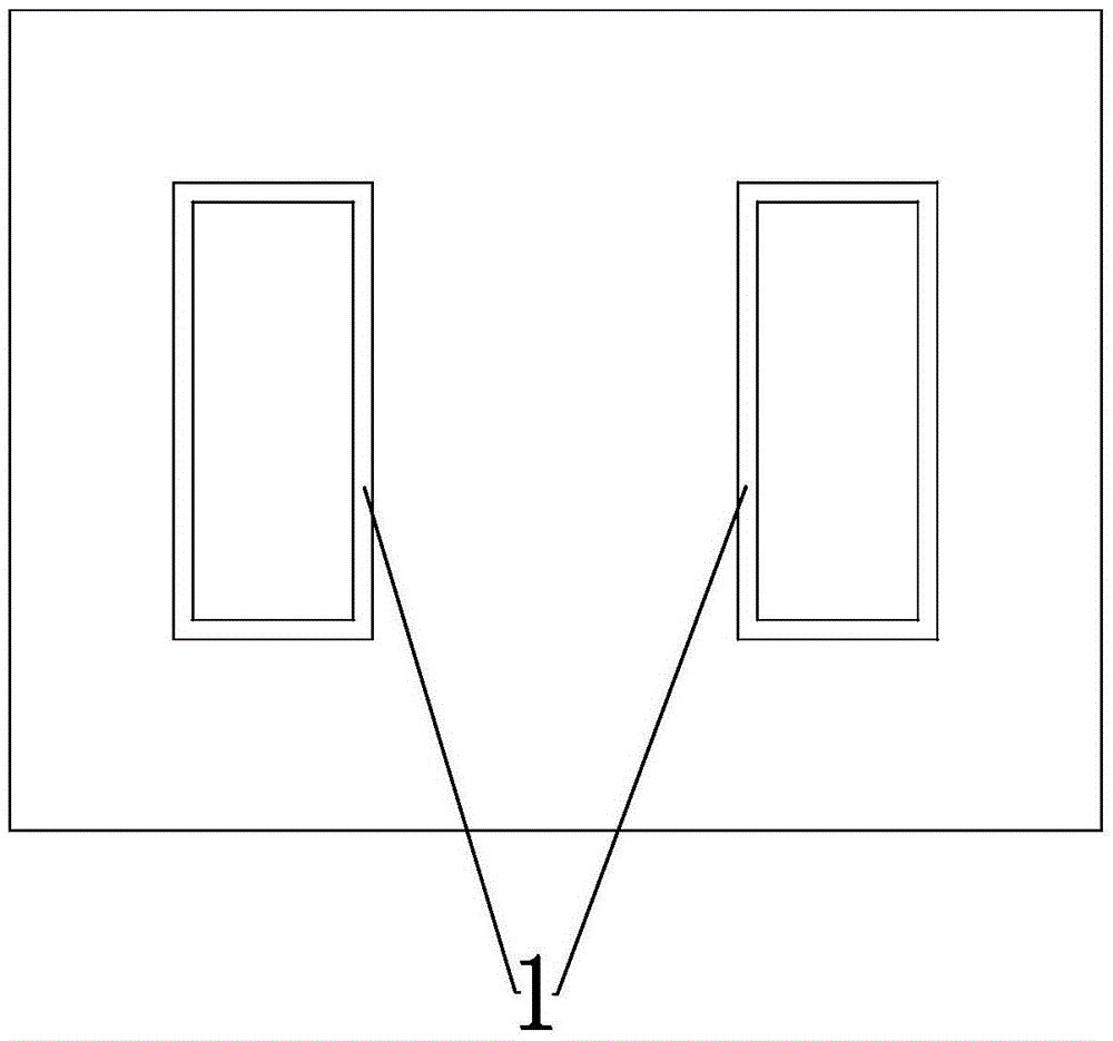
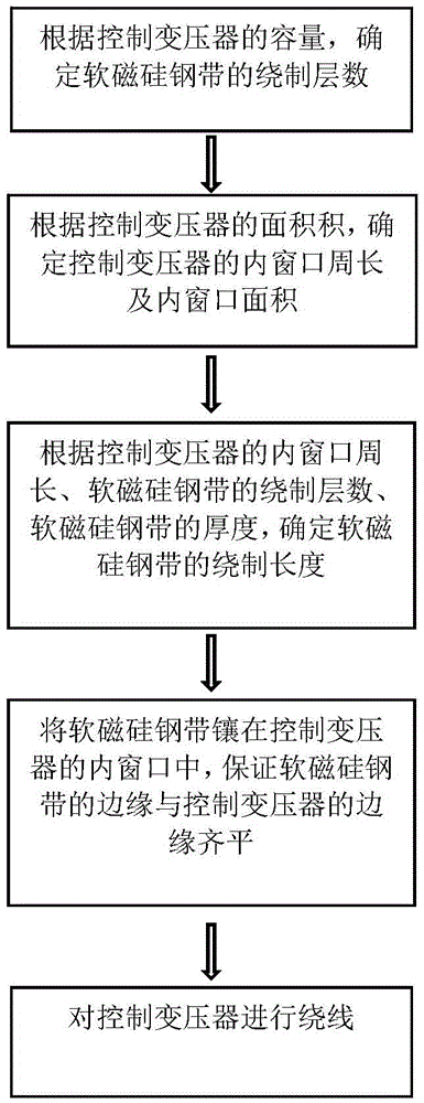
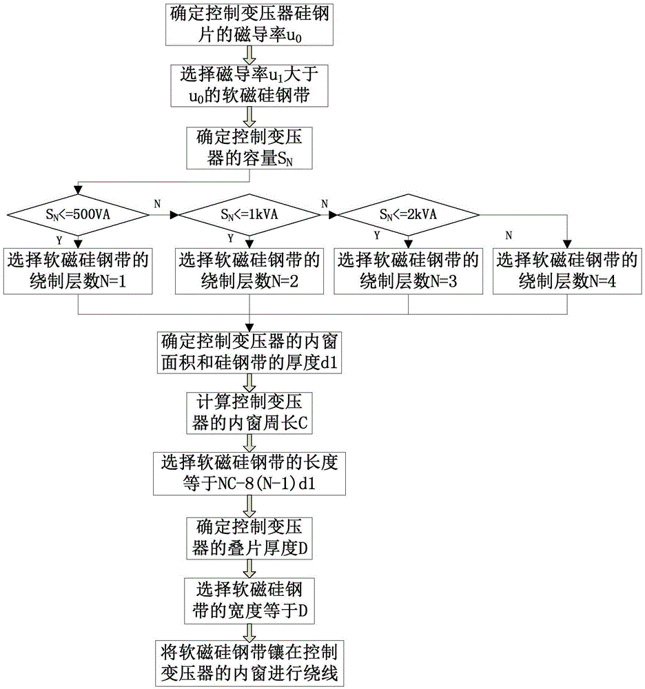
[0018] Please refer to figure 1 , figure 2 and image 3 , a magnetic flux leakage shielding method for a control transformer,

[0019] According to the capacity of the control transformer, the number of winding layers of the soft magnetic silicon steel strip 1 is determined;

[0020] Determin...


PUM


Abstract

The application discloses a magnetic leakage shielding method of a control transformer. The magnetic leakage shielding method comprises the following steps of determining winding layer number of a soft magnetic silicon steel strip according to the capacity of the control transformer; determining the perimeter of an inner window and the area of the inner window of the control transformer according to an area product of the control transformer; determining winding length of the soft magnetic silicon steel strip according to the perimeter of the inner window of the control transformer, the winding layer number of the soft magnetic silicon steel strip and the thickness of the soft magnetic silicon steel strip; and embedding the soft magnetic silicon steel strip in the inner window of the control transformer and then winding the control transformer, wherein the edge of the soft magnetic silicon steel strip is ensured to be flush with the edge of the control transformer. According to the magnetic leakage shielding method, the influence of a leakage magnetic field on a skin effect in a control transformer winding is reduced on the condition that the control transformer conforms to a corresponding load and stable power supply is ensured, the eddy-current loss in the winding during load running of the control transformer is effectively reduced, the service lifetime of an insulation layer of the control transformer is prolonged, and the effects of more efficiency and energy saving are achieved.

Description

technical field [0001] The disclosure relates to the field of transformer manufacturing in the power transmission and transformation industry, in particular to a method for shielding magnetic flux leakage of a control transformer. Background technique [0002] At present, control transformers are widely used in machinery and elevators, which has greatly increased the number of control transformers. When the control transformer is in operation, its loss is mainly composed of the current heat loss of the winding resistance, the eddy current loss in the winding wire, the circulation loss, the loss of the lead wire, and the loss of the structural parts. However, the control transformer produced by the current control transformer manufacturer is almost It is made of EI silicon steel laminations, and there is almost no magnetic flux leakage shielding for the eddy current loss caused by the magnetic flux leakage of the control transformer. It not only causes a large amount of powe...

Claims


Application Information

Patent Timeline
IPC IPC(8): H01F41/00H01F41/02H01F27/34
CPCH01F41/00H01F27/346H01F41/0213
Inventor 王祥根李世博林拥杰戴爱军
Owner NANTONG MILANTE ELECTRIC
Why Eureka
Try Eureka