Double-motor constant power synchronous control system free of rigid shaft connection

A technology of synchronous control and dual motors, which is applied in control system, AC motor control, multiple motor speed adjustment, etc. It can solve the problems of out-of-synchronization of output shaft position, large load, and inability to use constant power control, etc., to ensure position synchronization , the effect of improving work efficiency

Active Publication Date: 2016-04-27
WUHAN GUIDE ELECTRIC DRIVE TECH CO LTD +1
View PDF8 Cites 7 Cited by
  • Summary
  • Abstract
  • Description
  • Claims
  • Application Information

AI Technical Summary

Problems solved by technology

[0003] If there is no mechanical connection between the output shafts of the two motors, the load on the output shaft of one motor may be large and the load on the output shaft of the other motor may be large due to the uneven distribution of the weight when the heavy objects are jointly lifted. In a small case, at this time, if each motor changes the maximum speed linearly according to the current load torque on the output shaft and the rated torque of the motor, different maximum speeds will be obtained, which will eventually cause the two motors to The position of the output shaft is not synchronized, so it cannot be used normally. It is for this reason that when two motors without a rigid shaft connection are used to lift heavy objects together, constant power control cannot be used, and the maximum speeds of the two motors are simply controlled. It is set to the same value, generally the rated speed of the motor, which makes the lifting potential of the motor unable to be effectively tapped and reduces the working efficiency of the lifting system

Method used


Image

  • Double-motor constant power synchronous control system free of rigid shaft connection
  • Double-motor constant power synchronous control system free of rigid shaft connection

Examples


Embodiment Construction

[0017] The present invention will be further described below in conjunction with the accompanying drawings and embodiments.

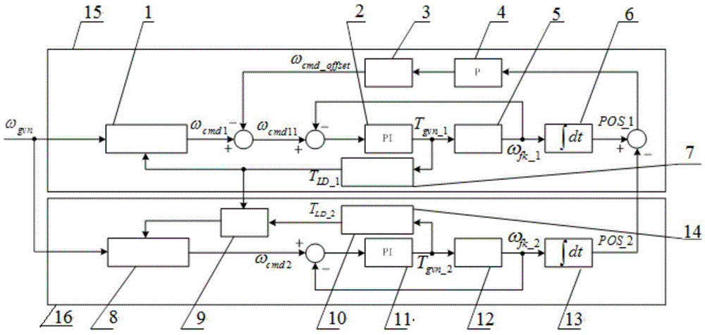
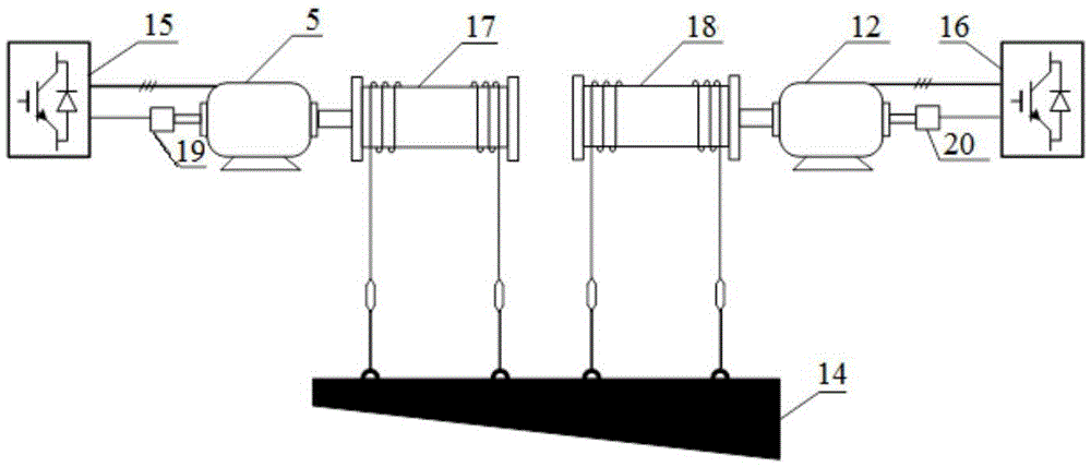
[0018] A dual-motor constant power synchronous control system without rigid shaft connection in this embodiment ( figure 1 ), including a master inverter 15 for driving the master motor 5 and a slave inverter 16 for driving the slave motor 12, the master inverter 15 includes a master maximum speed command generating unit 1, a master speed PI regulator 2, a master position control limiter Unit 3, master position control proportional unit 4, master speed variable position integral model 6, master load detection unit 7, slave maximum speed command generation unit 8, slave maximum load judgment unit 9, slave load detection unit 10, slave Speed ​​PI regulator 11, slave speed variable position integral model 13. Apply this system to two motors to jointly lift the same heavy object with uneven mass distribution 14( figure 2 ), the main motor 5 drives the ma...


PUM


Abstract

The invention discloses a double-motor constant power synchronous control system free of rigid shaft connection. Two motors free of rigid shaft connection are controlled by two frequency changers, so that constant power synchronization of the two motors is guaranteed. Host position control of a main frequency changer is combined with a slave maximum load torque breaking unit of a slave frequency changer, so that the two motors free of rigid shaft connection can realize constant power control, namely the maximum speeds of the two motors are determined according to the motor with the maximum load, and output shaft position synchronization of the two motors is guaranteed in the whole operational process. According to the system, the two motors free of rigid shaft connection can realize constant power control, namely the maximum speeds of the two motors are determined according to the motor with the maximum load, and the output shaft position synchronization of the two motors is guaranteed in the whole operational process, so that the work efficiency of the system is improved.

Description

technical field [0001] The invention relates to a dual-motor constant power synchronous control system, in particular to a dual-motor constant power synchronous control system without rigid shaft connection, which can dynamically adjust the maximum speed of two motors without rigid shaft connection according to the load size, and at The position synchronization of the two motors is maintained throughout the operation. Background technique [0002] At present, in the hoisting electrical control system in the hoisting field, in order to improve work efficiency, the maximum speed is often set according to the weight of the lifting weight. The easiest way is to allow the motor to run at the maximum speed when the weight is not hoisted (for example 1.5 times the rated speed of the motor), and run at the rated speed of the motor when lifting heavy objects. This method cannot judge the proportion of the lifting heavy objects to the rated load of the motor, so the maximum speed cann...

Claims


Application Information

Patent Timeline
IPC IPC(8): H02P5/46H02P27/04
CPCH02P5/46H02P27/04
Inventor 谢鸣李小松曾国庆毛荣芳
Owner WUHAN GUIDE ELECTRIC DRIVE TECH CO LTD
Why Eureka
Try Eureka